Tilt-and-Swing Front Board Mechanism¶
1. Purpose¶
The front board is the interchangeable plate that carries the pinhole disc at the scene-facing end of the container. This report specifies a new plate — the Tilt-Swing Board (TSB) — that replaces the flat pinhole plate and adds two axes of angular adjustment to the pinhole's pointing direction.
2. Mechanism Overview¶
2.1 Pinhole mechanism¶
The TSB assembly is a two-part drop-in replacement for the standard flat pinhole plate:
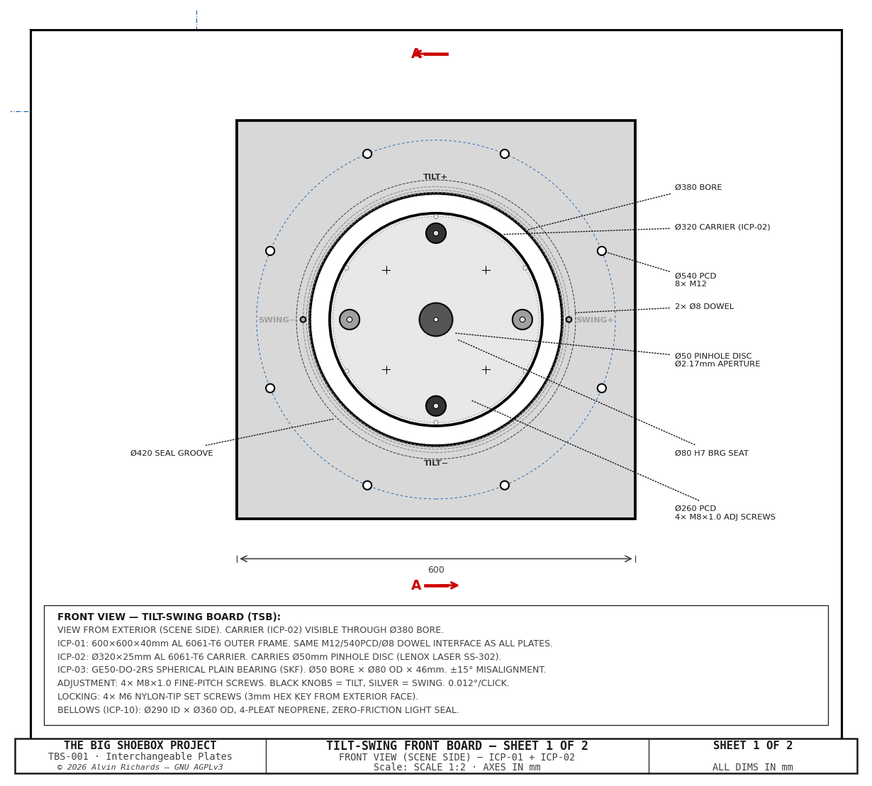
Sheet 1 — Front View (1:2 scale, scene side). Shows ICP-01 outer frame with bolt pattern, bore, carrier plate, adjustment knobs, pinhole disc, and section cut A-A.
2.2 Tilt Mechanism¶
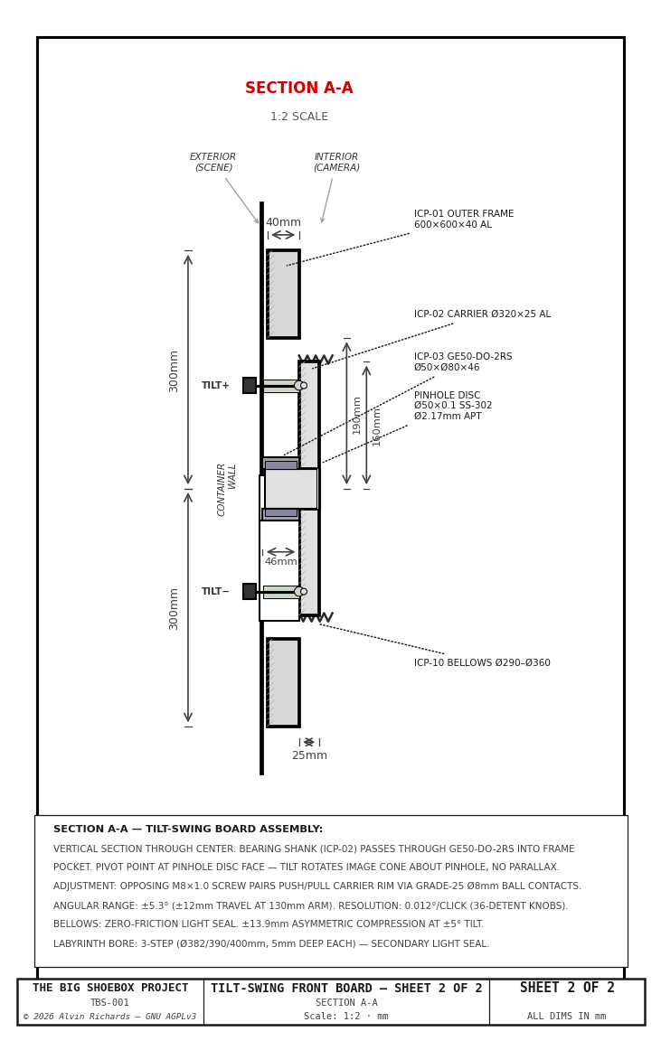
Sheet 2 — Section A-A (1:2 scale). Vertical section through center showing bearing pocket, carrier shank, bellows, adjustment screw mechanism, and pinhole disc.
WALL FRAME (fixed, welded to container)
│
├── ICP-01  OUTER ADAPTER FRAME  600×600×40mm Al 6061-T6
│    ├── Identical M12/540PCD/Ø8 dowel interface as all other plates
│    ├── Ø380mm central bore (passes ICP-02 carrier + 135mm clearance margin)
│    ├── Ø80 H7 × 50mm deep bearing seat pocket (interior face)
│    ├── 4× M8×1.0 fine-pitch adjustment screws with Delrin guide bushings
│    ├── 4× M6 nylon-tip locking set screws (cross-lock each adj screw)
│    ├── 6× M6 bellows outer flange attachment on Ø375mm PCD
│    └── 3-step labyrinth bore (Ø382/390/400mm) — secondary light seal
│
├── ICP-02  INNER CARRIER PLATE  Ø320×25mm Al 6061-T6
│    ├── Carries standard Ø50×0.1mm SS-302 pinhole disc (Lenox Laser)
│    ├── Ø52×3mm counterbore — identical to standard plate
│    ├── Spherical pivot: Ø50 k5 shank into GE50-DO-2RS bearing
│    ├── 4× 440C SS hemispherical ball-socket inserts on Ø260mm PCD
│    └── 6× M6 bellows inner flange attachment on Ø310mm PCD
│
├── ICP-03  GE50-DO-2RS SPHERICAL PLAIN BEARING
│    ├── SKF/INA/Kaydon GE50-DO-2RS (same bearing family as film plane)
│    ├── Bore Ø50mm | OD Ø80mm | Width 46mm | Misalignment ±15°
│    └── PTFE-lined self-lubricating — maintenance-free, chemistry-safe
│
└── ICP-10  BELLOWS (matte black neoprene/nylon)
     ├── ID Ø290mm → OD Ø360mm, free length 60mm, 4 pleats
     └── Accommodates ±13.9mm asymmetric compression at ±5° tilt
3. Movement Specification¶
| Axis | Control | Travel | Resolution | Image effect |
|---|---|---|---|---|
| Tilt | Top + bottom M8 screws (black knobs) | ±5.3° | 0.012°/click | ±219mm vertical image shift |
| Swing | Left + right M8 screws (silver knobs) | ±5.3° | 0.012°/click | ±219mm horizontal image shift |
| Compound | All 4 screws | ±3.7° per axis simultaneously | 0.012°/click | Diagonal shift + keystone |
Image shift formula: shift (mm) = f × tan(θ) = 2,362 × tan(θ)
| Board angle | Tilt image shift | Notes |
|---|---|---|
| 1° | 41mm | Very subtle — useful for fine composition |
| 2° | 83mm | ~3.5% of frame height |
| 3° | 124mm | ~5.2% — clearly visible on print |
| 5° | 207mm | ~8.7% — dramatic compositional shift |
| 5.3° (max) | 219mm | Mechanical hard stop |
4. Pivot Bearing: GE50-DO-2RS¶
The GE50-DO-2RS was chosen over cross-flexure and Cardan arrangements:
- Cross-flexure: two stacked stages needed for tilt + swing simultaneously; combined depth of ~60mm exceeds the 40mm plate budget; parasitic translation at compound angles
- Cardan joint: cross-spider projects beyond Ø350mm aperture; gimbal-lock risk near cross-axis; shaft seals at 4 points
- GE50-DO-2RS (chosen): single component handles both axes about a true pivot point; ±15° misalignment capacity (well above ±5.3° required); PTFE sliding surface is sealed, maintenance-free, and impervious to photographic chemistry; zero backlash under preload from opposing screw pairs
The pivot is located at the plane of the pinhole disc face (40mm forward of the bearing housing), so tilt rotates the image cone about the pinhole itself — no parallax error from pivot offset.
5. Adjustment Mechanism¶
Four M8 × 1.0 fine-pitch stainless screws, each terminating in a Grade-25 Ø8mm chrome steel ball seated in a hardened 440C SS hemispherical insert pressed into the carrier plate rim.
Angular resolution:
Arm radius (pivot → ball contact):    130mm
Screw pitch:                          1.0mm per turn
Linear travel ÷ arm radius:           1/130 rad/mm = 0.0077°/mm
Resolution per full turn:             arctan(1.0/130) = 0.44°
Detents per turn (36-detent knob):    36
Resolution per click:                 0.44° / 36 = 0.012° per click
Full ±5° range from center:           ~410 clicks (11.4 turns)
Mechanical hard stop:                 ±12mm travel = ±5.3°
Knob identification: - Top and bottom screws → TILT axis → black anodised knobs, engraved TILT+ / TILT− - Left and right screws → SWING axis → natural/silver anodised knobs, engraved SWING+ / SWING−
Operation: To tilt upward, turn TILT+ clockwise (pushes top of carrier away from frame) and TILT− counter-clockwise (releases tension on bottom) by equal amounts. This keeps the pivot point centered on the bearing at all times.
6. Light Sealing¶
The bellows (ICP-10) is the primary seal — zero friction, zero wear, accommodates the full angular range with no light leakage:
- 4-pleat accordion geometry tolerates ±13.9mm asymmetric compression at ±5° tilt (left side compresses, right side extends by equal amounts)
- Inner and outer attachment flanges are sealed with Ø3mm neoprene cord gaskets — same specification as the wall-frame seal used on all plates
- The ICP-01 bore has a 3-step machined labyrinth (Ø382 / Ø390 / Ø400mm, 5mm deep each) — secondary seal preventing any direct light path even if the bellows flange lifts at extreme angles
Why bellows over EPDM wiper seal: A wiper seal pressed against the tilting disc edge creates variable friction at different angles, giving inconsistent feel. Bellows are zero-friction, standard photographic practice, and self-certify light-tightness by construction.
7. Locking for Long Exposures¶
After setting the desired angle, tighten the 4 × M6 nylon-tip set screws (one per adjustment screw, accessed with a 3mm hex key from the exterior face). The nylon tip binds against the M8 shank without marring the threads.
The combined stiction of: 1. M6 lock screws binding M8 adjustment screws 2. Opposite screw pair compressive preload 3. PTFE bearing surface stiction
provides robust position-holding for exposures of 20–90 minutes under ambient wind loads.
8. Plate Swap Procedure¶
The TSB assembly swaps in/out of the same wall frame as the standard pinhole plate. No special tooling required beyond an M12 socket and 3mm hex key.
- Loosen 4× M6 locking set screws (3mm hex key)
- Zero all 4 adjustment knobs to 0° using the calibration scales
- Remove 8× M12×45 SHCS bolts
- Pull TSB assembly from wall frame (dowel pins release with light pull)
- Fit standard flat pinhole plate — locate on same Ø8mm dowel pins, torque M12 bolts to 65 Nm
Swap time: approximately 10 minutes.
9. Board-Only Distortion Renders¶
The following renders show the isolated effect of the tilt-swing front board on the projected image, with the film plane held flat at the far wall. The world scene is a regular grid at three depths (near: 7m, mid: 22m, far: 102m from pinhole) plus a human-figure reference and horizon line.
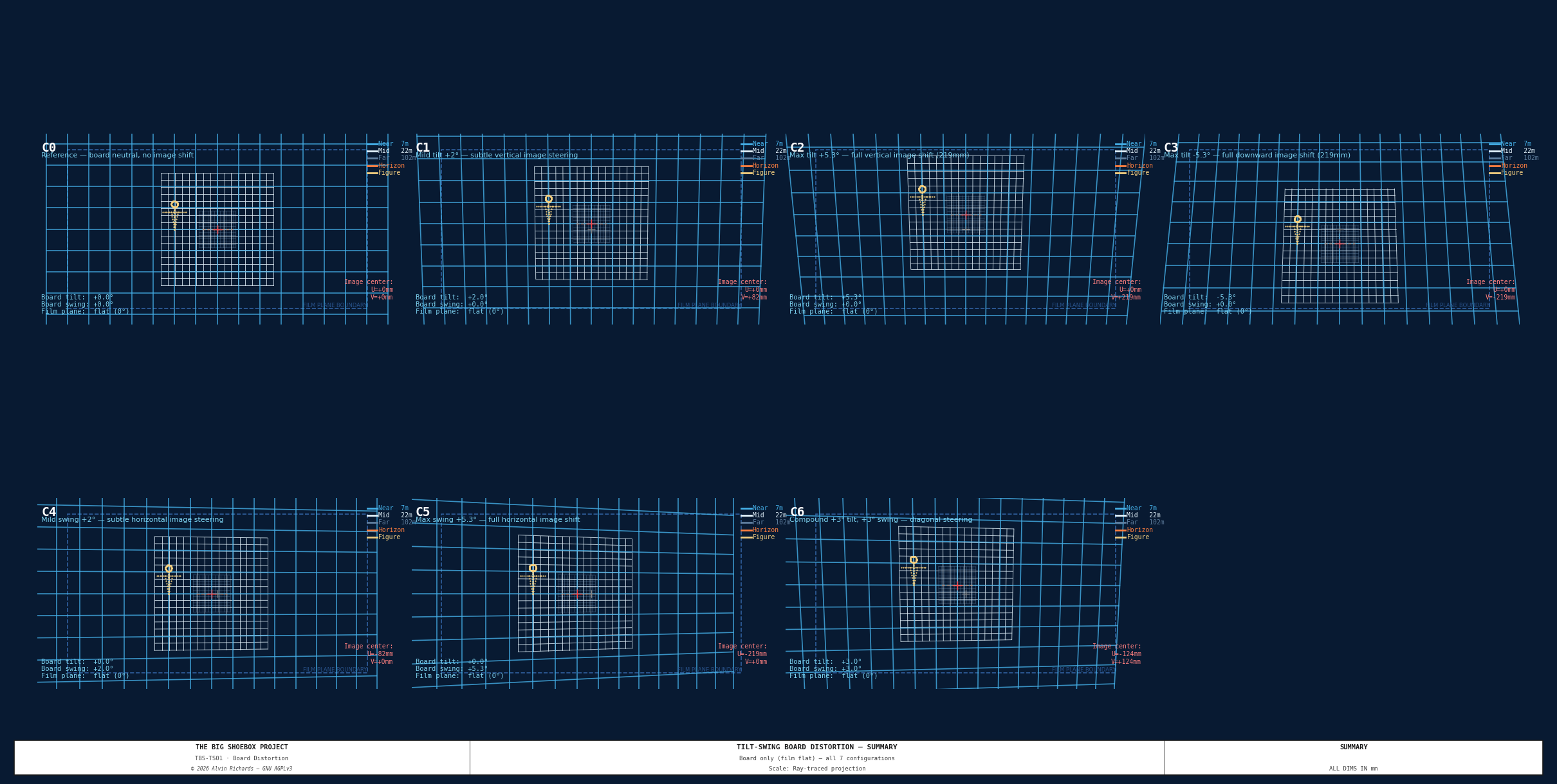
The board's ±5.3° range produces up to 219mm of image shift — enough to steer composition without any film plane movement.
| Config | Board Tilt | Board Swing | Effect |
|---|---|---|---|
| C0 | 0° | 0° | Reference — no shift |
| C1 | +2° | 0° | Subtle vertical steering |
| C2 | +5.3° | 0° | Max vertical shift (+219mm) |
| C3 | -5.3° | 0° | Max downward shift (-219mm) |
| C4 | 0° | +2° | Subtle horizontal steering |
| C5 | 0° | +5.3° | Max horizontal shift |
| C6 | +3° | +3° | Compound diagonal steering |
A detailed analysis of the optical distortions can be found here.
The red cross (+) marks the projected image center; gray cross marks the nominal center. Note the grid remains rectilinear — the board translates the image cone without introducing geometric distortion. Distortion only appears when combined with film plane tilt/swing (§10).
10. Combined Distortion Renders¶
The following renders show the combined projection of both systems operating simultaneously. The world scene is a regular grid at three depths (near: 7.4m, mid: 22.4m, far: 102.4m from pinhole) plus a human-figure reference and horizon line.
The projection model applies two sequential transformations:
Step 1 — Front board rotation:
Board tilt α and swing β rotate the effective world coordinate system:
W' = Ry(−β) · Rx(−α) · W_world
Step 2 — Film plane intersection:
The tilted film plane (film tilt θ, film swing φ) is defined by anchor point r₀=(0,0,2362) and normal n = Ry(φ)·Rx(θ)·[0,0,−1]. The image point is:
t = (n·r₀)/(n·d); F = t × d
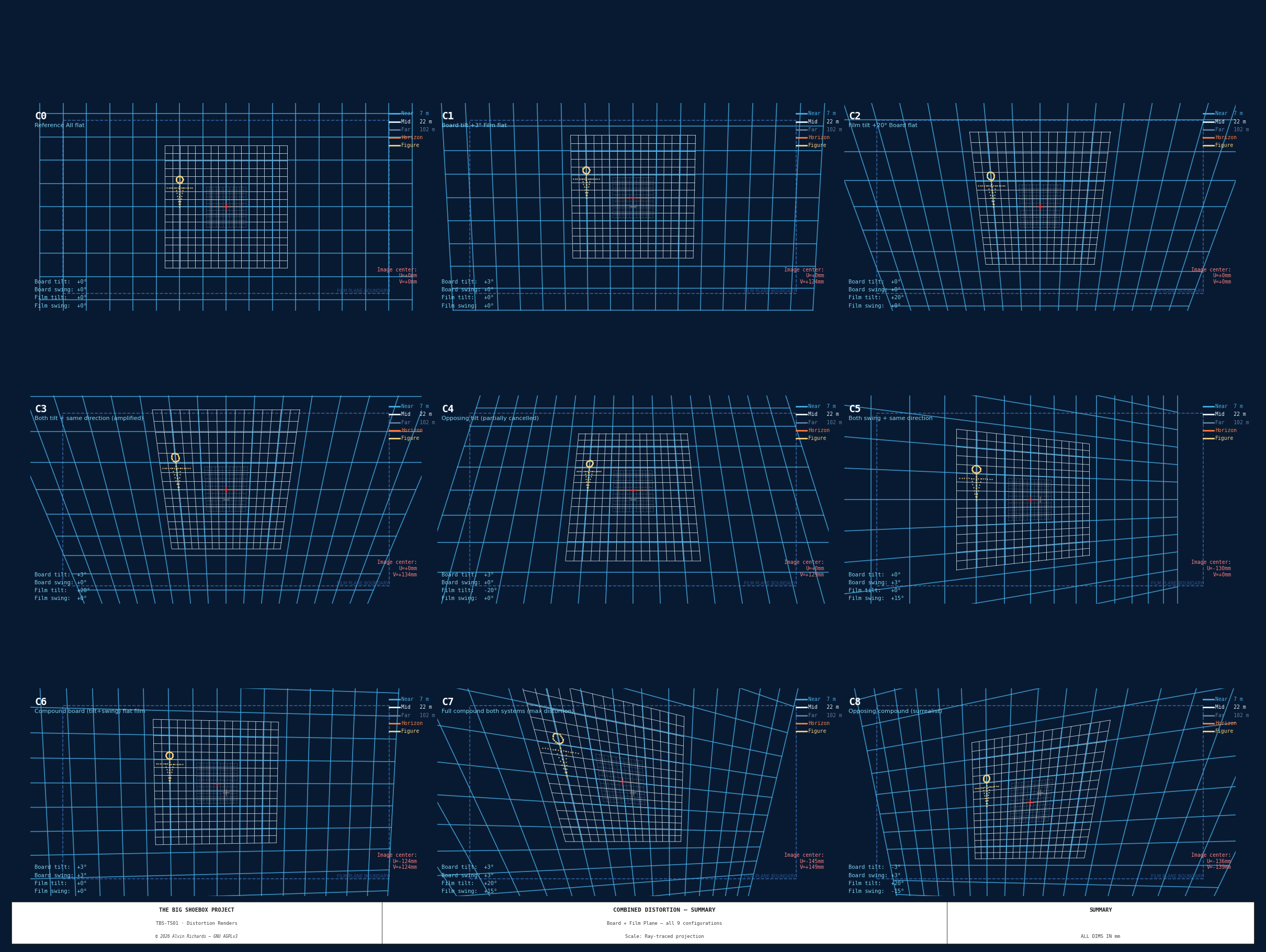
The red cross (+) marks the projected image center; gray cross marks the nominal center.
Detailed renders can be found in the full analysis
11. Machining Tolerances¶
| Feature | Nominal | Tolerance | Importance |
|---|---|---|---|
| ICP-01 bearing seat bore Ø80 | Ø80.000 | H7: +0.030/0.000 | Bearing outer ring press-fit |
| ICP-02 bearing shank Ø50 | Ø50.000 | k5: +0.013/+0.002 | Bearing inner ring fit |
| ICP-02 counterbore Ø52 | Ø52.000 | H7: +0.030/0.000 | Concentric with shank to 0.05mm |
| ICP-02 shank perpendicularity | — | 0.05mm/100mm | Sets optical zero |
| ICP-08 hemispherical socket Ra | — | Ra 0.4 (ground) | Ball articulation smoothness |
| ICP-01 bolt holes M12 PCD | Ø540.000 | ±0.1mm positional | Must match wall frame exactly |
| ICP-01 dowel holes Ø8 | Ø8.000 | H7: +0.015/0.000 | Plate registration repeatability |
| Adj screw arm radius | 130.000 | ±0.25mm | Calibration scale accuracy |
12. Parts List¶
12.1 Structural¶
| Item | Spec | Source A | Source B | Est. cost |
|---|---|---|---|---|
| GE50-DO-2RS bearing | SKF, 50mm bore | Bearing Headquarters, Buena Park CA (bearingheadquarters.com) | Applied Industrial, Los Angeles | ~$90 |
| Al 6061-T651 plate (ICP-01) | 620×620×45mm (24"×24"×1.75") | Online Metals (onlinemetals.com) | Metal Supermarkets, Chatsworth CA | ~$125 |
| Al 6061-T6 round bar (ICP-02) | Ø340mm×35mm (13.5"OD×1.5") | Metal Supermarkets, Chatsworth CA | Online Metals | ~$100 |
| M8×1.0 SS A4 SHCS | M8×1.0×80mm | Bolt Depot (boltdepot.com) | Pacific Coast Bolt, Anaheim CA | ~$3 ea |
| Delrin/POM rod (bushings) | Ø30mm×200mm | McMaster-Carr, Santa Fe Springs CA (#8573K75) | Amazon Industrial | ~$20 |
| Ø8mm Grade 25 chrome steel balls | 52100 bearing steel, 10-pack | McMaster-Carr (#9528K22) | Precision Balls Inc. | ~$14/pack |
| M6×1.0 nylon-tip set screws | SS316, M6×20mm | McMaster-Carr (#91375A187) | Fastenal (SoCal branches) | ~$14/pack-10 |
| 440C SS round bar (socket inserts) | Ø20mm×100mm | McMaster-Carr (#1765T17) | Metal Supermarkets | ~$28 |
| M12×45 SHCS SS A4 | 8 off | McMaster-Carr (#92290A198) | Bolt Depot | ~$20/pack-5 |
| M16×55 SHCS SS A4 | 1 off | McMaster-Carr (#92290A254) | Bolt Depot | ~$5 |
| Ø8 m6 SS303 dowel pins | Ø8×40mm | McMaster-Carr (#97395A437) | Fastenal | ~$9 ea |
| Loctite 638 retaining compound | 10mL | McMaster-Carr (#1832A1) | Home Depot (local) | ~$22 |
12.2 Light Seal¶
| Item | Spec | Source A | Source B | Est. cost |
|---|---|---|---|---|
| Photographic bellows (custom) | Ø290 ID × Ø360 OD × 60mm, 4-pleat, matte black neoprene | Micro-Tools (microtools.com) — custom order | Ames Camera Repair (custom bellows) | ~$80–150 |
| Neoprene cord seal Ø3mm | 70 Shore, 1.5m (for Ø420 loop + flange gaskets) | McMaster-Carr (#1834K22) | Grainger (LA branches) | ~$18 |
12.3 Finishing & Fabrication¶
| Item | Spec | Source | Est. cost |
|---|---|---|---|
| Hard anodise (ICP-01 exterior) | MIL-A-8625 Type III, 0.025mm | Pac-Nor Anodizing, Chatsworth CA | ~$80–120 |
| Black anodise (ICP-02, knobs) | Type II | Aero Finishing, Burbank CA | ~$60–90 |
| CNC machining (ICP-01 + ICP-02) | All Al parts | Fictiv (fictiv.com) / ProtoLabs | ~$800–1,500 |
| Knurled knob stock Ø40mm | Al, 4 off | Jergens (#49525) or machine from bar | ~$15 ea |
| Angular scale engraving | Al 80×15×2mm, 2 off | LaserPros, Chatsworth CA | ~$35–50 |
12.4 Cost Summary¶
| Category | Low estimate | High estimate |
|---|---|---|
| Hardware + bearings + seals | $420 | $580 |
| CNC machining | $800 | $1,500 |
| Anodising | $140 | $210 |
| Knobs + scales | $110 | $150 |
| Total | ~$1,470 | ~$2,440 |
13. Maintenance¶
| Interval | Task |
|---|---|
| Before each session | Check all four M6 locking set screws are released before adjustment |
| Before each session | Verify bellows (ICP-10) is intact — no tears, flange gaskets seated |
| Before each session | Zero-check calibration scales against spirit level |
| Monthly | Inspect M8 adjustment screw ball-socket contacts for wear |
| Monthly | Check Delrin guide bushings for cracking or swelling |
| Every 6 months | Inspect GE50-DO-2RS bearing for play — replace if radial slop exceeds 0.1mm |
| Every 6 months | Check labyrinth bore steps for accumulated dust or debris |
| Annually | Inspect bellows pleats for fatigue cracking (especially at max-angle fold lines) |
| Annually | Verify M12 bolt torque at wall frame interface (65 Nm) |
| Annually | Check dowel pin fit — pins should release with light pull, no binding |
14. Source References¶
- SKF GE50-DO-2RS Spherical Plain Bearing — Bearing specifications, misalignment capacity, and PTFE liner properties.
- Lenox Laser Precision Pinholes — Pinhole disc fabrication (Ø2.17mm, SS-302 shim).
- Micro-Tools Custom Bellows — Custom photographic bellows fabrication.
- Film Plane Mechanism Report — Rear standard mechanism and combined distortion analysis.
- Pinhole Report — Wall frame and interchangeable plate interface specification.