Equipment Layout — Shadow-Free End-Zone Design¶
1. Design Principle — Shadow-Free End Zones¶
The optical cone from the pinhole narrows as it approaches the pinhole wall and widens as it approaches the film plane. Any equipment placed inside the cone casts a shadow on the film plane, producing an unexposed void in the image.
Solution: Reduce the active film plane from the full 5,893mm container width to a 4,389mm span. This creates two provably shadow-free end zones — one at each end of the container — where equipment can be placed at any depth without entering the optical cone. The right end zone contains a 2×2 IBC stack, leaving the left zone to contain the light trap drum.
Zone Definitions¶
| Zone | X range | Shadow-free? | Equipment assigned |
|---|---|---|---|
| Left end zone | 0–260mm | YES at all depths | Light trap drum, hinged panel (stepped) |
| Optical zone | 260–4,649mm | NO | Film plane, rails, processing tray, perimeter walkway |
| Right end zone | 4,649–5,893mm | YES at all depths | IBC tanks (2×2 stack: 2× Blue, 1× Brown, 1× Waste) |
| Pinhole wall face | Y=0 surface | YES (cone collapses to point) | Electrical panel, battery, pump |
2. Equipment Positions¶
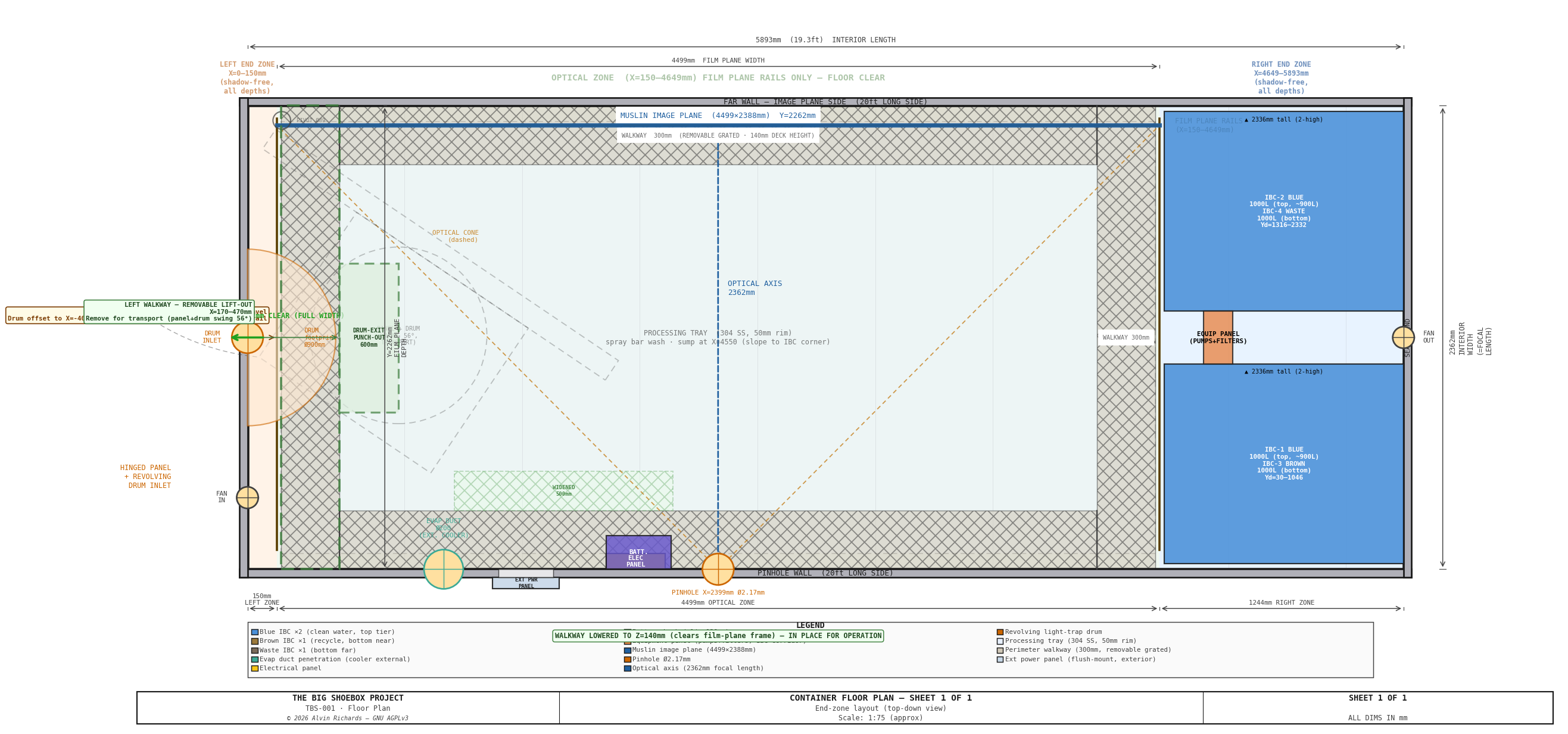
Overall floorplan can be seen below. Its essentially split into three areas, left, center and right which are discussed below.
Floor plan
2.1 Left End Zone¶
| Item | X (mm) | Yd (mm) | H (mm) | Notes |
|---|---|---|---|---|
| Hinged panel (stepped) | 0–40 (corner) / 0–120 (center) | 0–2,362 | 0–2,388 | Stepped profile: 40mm corners, 120mm center (drum housing). Swings ~56° about the Ø89 pivot for transport. |
| Light trap drum | −850–50 | 731–1,631 (centered at CW/2=1,181mm) | 130–2,250 | Centered at X=−400 (offset into container); integrated into panel center zone; rotary drum entry |
2.2 Pinhole Wall Face¶
| Item | X (mm) | H (mm) | Notes |
|---|---|---|---|
| Evaporative cooler | 700–1,300 | ground | Hessaire MC18M, 120V AC 85W (97W on 12V bus via inverter); ground-placed outside, flex duct to wall stub at Z=1,900mm |
| Cooler inverter (Cct E) | 1,910–2,030 | 1,180–1,415 | Victron Phoenix 12/375 GFCI, wall-mounted below the EP (12V→120V for the cooler) |
| Electrical panel | 1,910–2,210 | 1,500–2,100 | IP65, wall-mount (stacked above the battery bank; clears the upper transport-stay anchor) |
| Battery bank (1× 100Ah LiFePO4 Core, 260×169×211mm; stacked provision for 2nd) | 1,829–2,089 | 160–371 | Skinny EP column, vertically stacked (side busbar); clears the optical cone |
| Solar charge controller | Within panel | — | Mounted inside enclosure |
| Cable trunking | Along wall face, H=1,800mm | — | Full length |
| Blue supply pipe → spray bar | along wall to X=2,454 | — | Rigid 1/2" PVC Sch-40 from the corridor pump panel to the spray-bar feed; pumps themselves are on the plumbing panel in the IBC corridor (§2.4 / Plumbing Report) |
2.3 Optical Zone¶
Rail slots in floor/ceiling. Film plane frame spans this zone (nominal far position).
| Item | X (mm) | Yd (mm) | H (mm) | Notes |
|---|---|---|---|---|
| Processing tray (2 panels, 304 SS) | 280–4,629 | 80–2,280 | 0–50 | 50mm rim; 20mm clearance to film plane rails; sump well at X=2,386, Yd=80 with P-04 suction pickup to 3W-DV-02. On tapered HDPE shim strips. Permanently installed. |
| Perimeter walkway (4 sections, removable) | 280–4,629 | 0–300 / 2,062–2,362 | 0–140 | 300mm wide, 140mm deck height (115mm support + 25mm grate). Near/far: wall-cantilevered 8mm gusset brackets at 457mm centers. Right: cantilever rectangle (2×1×0.120in steel frame) off the IBC frame + wall cleats; grate on 1×1×3/16in L-angle bearers. Left: removable lift-out grate on 5 floor-leg cantilever brackets bolted to bare floor outside the tray (arms to X=470, 3 extended to X=770 on the punch-out; the panel occupies this end wall), 25mm grating. Left corners: butt joint (no miter). No tray contact (left brackets bolt to bare floor outside the tray). Floor-leg arm (Z=75–115) clears the 50mm tray rim and the Z60 spray bar by 15mm. |
The processing tray sits below the film plane carriage blocks (minimum Z=140mm at maximum 40° tilt; the lower max angle only increases clearance), providing 90mm clearance above the tray rim. The tray does not contact or interfere with the U-channel depth rails.
2.4 Right End Zone¶
2×2 IBC stack — right-justified flush to the far end wall. Four IBCs in two columns (25mm clearance from zone boundary), separated by a
270mm plumbing corridor between near and far columns. IBC wall clearance is 30mm on each side.
| Item | X (mm) | Yd (mm) | H (mm) | Notes |
|---|---|---|---|---|
| Blue IBC-1 (900L fill, top near) | 4,674–5,893 | 30–1,046 | 1,168–2,336 | Near column top; restraint frame |
| Blue IBC-2 (900L fill, top far) | 4,674–5,893 | 1,316–2,332 | 1,168–2,336 | Far column top; restraint frame |
| Brown IBC-3 (recycle buffer, bottom near) | 4,674–5,893 | 30–1,046 | 0–1,168 | Near column bottom; recycled wash/fix |
| Waste IBC-4 (waste, bottom far) | 4,674–5,893 | 1,316–2,332 | 0–1,168 | Far column bottom; sealed waste collection |
3. Floor Plan and Line-of-Sight Diagrams¶
Optical line-of-sight
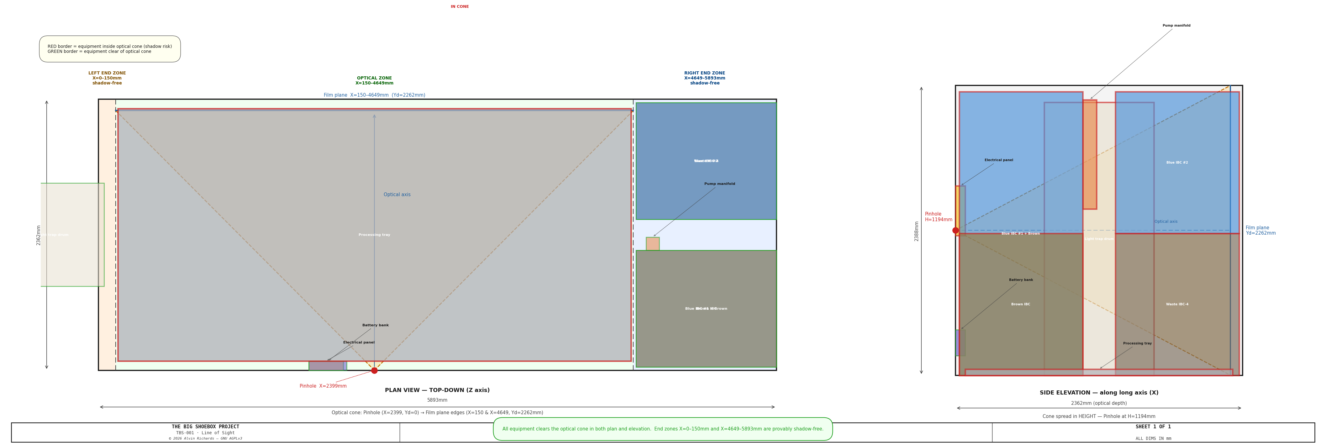
The line-of-sight analysis confirms zero equipment items intersect the optical cone in either the plan (top-down) or elevation (side) view.
4. Why IBC Y-Stacking (Front-to-Back)¶
In the current layout the entire right end zone is X-clear from X=4,649mm to the end wall — all four tanks occupy the same X column in a 2×2 arrangement (two columns along Y, two tiers high).
| Arrangement | X span used | Max Y depth |
|---|---|---|
| Side-by-side (X-spread) | 2,400mm | 1,116mm |
| Y-stacked, right-justified (chosen) | 1,219mm | 2,302mm |
The 2×2 stack gives a 1,219mm X footprint (= IBC cage width), right-justified to the far end wall. The zone itself is only 1,244mm wide, so the IBCs fit with 25mm clearance on the zone boundary side. The two columns are separated by a 270mm plumbing corridor, with 30mm wall clearance on each side.
5. IBC Stacking Frame — Design Specification¶
A welded mild steel restraint-only frame holds the 2×2 IBC stack (4× 1,000L caged composite totes — two columns, two tiers each, direct-stacked) as a single unit. The totes stack cage-on-cage, so the frame does not carry vertical load — it only restrains them for transport (front retaining bars + D-ring lashing).
| Item | Specification |
|---|---|
| Frame material | 2×2×0.120in steel (A500) |
| Frame type | RESTRAINT-ONLY deep 4-leg box — the 1,000L caged totes direct-stack cage-on-cage (no load-bearing deck), so the frame only restrains them |
| Uprights | 4 full-height corridor uprights (Yd 1046/1266) — a front pair at X≈4654 + a back pair 450mm behind at X≈5104, tied by top + bottom rings — on 150×150×12mm floor flange feet (4× M12 each); define the 270mm plumbing corridor |
| Front retaining bars | 4× 50×20×3 RHS at the IBC front (Z560 + Z1760), seated in the 25mm gap to the film rail — stop the totes sliding out the front; each bar's wall end drops into a Simpson-style joist hanger (×4) |
| Wall attachment | each joist hanger is through-bolted (4× M12) to a 100×135×8mm exterior backing plate (×4, hex heads outside) that spreads the load into the thin corrugated side wall |
| Lashing points | 1½" weld-on rings on the front bars (3,333 lb / ~1,512 kg assembly WLL, 2" strap-limited); ratchet straps pass over each stack and tie down to them |
| Total stacked height | 2,336mm (2× 1,168mm direct-stack) — 52mm ceiling clearance |
| Panel mount | the deep box carries the (forward) Corridor Plumbing Panel + drain-riser spine on its back uprights, and the right-walkway cantilever arms on its front uprights |
| Surface finish | Gray oxide primer + flat black powder coat (interior) |
| Approx. weight | ~90kg (4 uprights + rings + 4 feet + front bars + hangers + exterior wall plates + rear-panel brackets) |
| Approx. cost | USD $1,309–$1,872 (local mild steel fabrication) |
Why 1,000L caged composite (all four totes):
All four positions use the 275-gal (≈1,000 L) caged composite tote — the only food-grade, 48×40-footprint tote stocked. "600 L" / "1,000 L" are fill levels, not tote sizes.
| IBC type | H (mm) | Stacked pair | Ceiling clearance |
|---|---|---|---|
| 1,000L caged composite | 1,168 | 2,336mm | 52mm |
The 52mm headroom is tight but transport-validated: the loaded-transport CG sits at Z=1,341mm (static sideways tip threshold ≈41°, ≈21% of the ISO gross limit) — see the weight-distribution report.
Raw material suppliers:
| Item | Supplier | Notes |
|---|---|---|
| 2×2×0.120in steel (A500) | Pacific Coast Steel, Santa Fe Springs CA | A500 Grade B; ~$4/linear foot |
| Weld-on lashing rings (×8) | McMaster-Carr #3028T31 | 6,600 lb/ring; 3,333 lb assembly (2" strap-limited) |
| M12 bolts (wall-hanger through-bolts ×16 + front-bar cleats ×8) | McMaster-Carr or local hardware | SS A2-70; M12×65 through-bolts (span 8mm plate + corrugation + 4mm hanger) for the exterior plates, M12×40 for the front-bar cleats |
| Simpson-style wall joist hangers (×4) | Simpson Strong-Tie or local | folded 4mm plate, through-bolted to exterior backing plate |
| Exterior wall backing plates (×4) | Metal Supermarkets / local | 100×135×8mm steel, hex heads outside |
6. Left End Zone — Simplified Layout¶
The left end zone contains only the light trap drum and the hinged panel — providing unobstructed egress at the cargo door end.
6.1 Stepped Panel and Swing Pivot (Transport Mode)¶
The hinged panel has a stepped profile: 40mm thick at the corner zones and 120mm thick at the center zone where the light trap drum is mounted. For transport the panel + drum SWING ~56° about a vertical Ø89×8mm CHS pivot post (sharing the film-plane far-left upright), carrying the punch-out bay inboard of the door plane. Two narrow strips stay fixed at the door plane; the cargo doors close outboard of the fixed near strip.
| Position | Description | Doors clear? |
|---|---|---|
| Operational (0°) | Panel closed at the door plane; the B2 punch-out bay protrudes ~890mm outside | No — the doors stay open during camera operation |
| Transport (swung 56°) | Panel + drum revolved about the pivot, swept inboard | Yes — true minimum clearance to the closed door is +59mm |
A fixed welded door frame (2×2×0.120in steel SHS) provides the EPDM seal landing. The panel seals against this frame with the Southco C2-33 cam latches and 20mm EPDM gaskets in the closed (latched) position; the latches release to free the seals before the swing.
6.1.1 Swinging Panel Light Seal Design¶
The swinging panel seals against the fixed door frame in its operational (closed) position via five light-tight paths — panel perimeter, the two swing-cut seals, the bottom and top frame seal lips, and the Ø900 housing-surround ring — all 20mm EPDM, compressed by the four Southco C2-33 cam latches and released before the swing. See Hinged Panel Report §6 — Light Seal Design for the full per-path seal table and the dark-adaptation verification check.
6.2 Evaporative Cooler Transport Stowage¶
The evaporative cooler (Hessaire MC18M) sits on the ground outside the container during operation, connected to the wall penetration via Ø200mm flex cord and powered from the interior inverter (Circuit E, 120V AC). It must be stowed inside the container for transport.
Stowage position: On the near walkway grating in the wide section. The cooler sits on a 12mm plywood base plate (508×254mm) that distributes the load across the grating and prevents the housing from catching in the grate openings. The wide section fully contains the cooler depth with ~246mm clearance — no overhang into the processing tray zone. The lighter (16 lb) unit also eases the handling.
Securing: Two 25mm ratchet straps loop over the cooler and hook to the nearest cantilever bracket arms. Two aluminum angle cleats (25×25×3mm, 100mm long) screwed to the base plate prevent lateral sliding.
| Parameter | Value |
|---|---|
| Stowage zone | X=1,450–2,009mm, Yd=0–305mm (near walkway wide section) |
| Cooler footprint | 508×254mm (long axis along X) |
| Cooler height on grating | 711mm (top at Z=861mm) |
| Weight (dry) | ~7.3 kg (16 lb) |
| Securing | 2× ratchet straps to bracket arms |
| Base plate | 12mm ply, 508×254mm |
| Clearance to panel swing sweep | ~55mm (the swing reaches X≈1,395 in the near-walkway zone; the cooler at X=1,450 clears it) |
See Walkway Diagram — Sheet 1 for stowage position in plan view.
7. Plumbing and Electrical — Pinhole Wall Routing¶
Electrical services and the Blue supply pipe route along the pinhole wall face; the Corridor Plumbing Panel (pumps) sits in the IBC corridor (right end zone). No conduit, pipe, or cable runs through the optical zone.
Plumbing: The corridor pumps (P-01 Blue supply, P-02 Brown recycle, plus the P-05/P-03 waste-drain pumps) mount on the Corridor Plumbing Panel in the 270mm IBC plumbing corridor (right end zone), at the tote stack — so the pump↔tote runs are short. The Blue supply pipe runs from P-01 along the pinhole wall to the spray-bar feed in the optical zone (~4m coiled flex to the rolling beam); the tray drain returns from the sump to P-04 on the panel. P-02 (Brown filter feed) and the 3-stage filter stack are on the Pinhole Wall Plumbing Panel on the pinhole wall face. See the Plumbing Report for the full plumbing layout.
Electrical conduit: 40×25mm PVC trunking along the full container length on the pinhole wall face. Branch drops at each circuit termination. All circuits ≤ 9m — within voltage-drop budget for 12V DC with 10 AWG wire. The pump circuit (C) is switched at the master pump switch on the EP; the corridor panel carries only its 12V distribution block.
Solar inlet + shore power: NEMA 5-15R weatherproof inlet on exterior of pinhole wall.
8. Water Capacity Summary¶
All four positions are identical 1,000L caged composite IBCs — the 622L / 900L working fills are fill levels, not tote sizes (a 600L caged tote does not exist). Each tote's fill swings between the two ends of a resupply cycle:
| IBC (identical 1,000L tote) | Role | Camera ready | Supply exhausted |
|---|---|---|---|
| Blue ×2 (stacked) | Clean wash supply | 1,800L (2× 900L) | 0L |
| Brown | Recycled wash / fix buffer | 0L | 622L |
| Waste (sealed) | Waste collection | 0L | 622L |
| Total in system | — | 1,800L clean | 1,245L used |
A session starts camera-ready with both Blue totes full (900L each) and the Brown/Waste totes empty; the supply is exhausted when the Blue totes are empty. The collection totes hold ~1,245L of the 1,800L Blue supply — the rest is open-process loss (~465L; wet-print carryout, evaporation, unrecovered residual) plus a sub-print dreg (~110L).
Print capacity. The 1,800L nominal load supports ~15 prints per resupply; filling Blue toward the tote's physical maximum (~1,900–2,000L) raises this to ~15–16 (transport-validated, Weight Report §4.4), and on-site top-up via the X1 / X3 / X4 bulkhead ports extends it further. See Processing System Report §4 for the full water balance, max-fill, and top-up analysis, and the full water circuit design.
9. Egress Safety Assessment¶
When the hinged panel is opened 180° from the inside, the light trap drum (mounted in the panel center zone) swings outward with the panel. With the waste drums eliminated, the entire left end zone floor is clear.
9.1 Egress Gap¶
| Measurement | Value |
|---|---|
| Clear passage width | 2,362mm (93") — full container width |
| At door frame | ~2,362mm (full frame opening) |
| Obstructions in egress path | None |
Human factors reference:
- Average male shoulder width: ~460mm (18")
- Standard doorway minimum (IBC/IRC): 762mm (30")
- Emergency egress minimum: 610mm (24")
The 2,362mm passage exceeds all minimums by more than 3×. No equipment narrows the egress path at any point. The elimination of waste drums from the left end zone provides completely unobstructed access to the cargo doors.
9.2 Hinge Door Swing Clearance¶
The panel + drum swing about the Ø89 pivot — ~56° inboard for transport (the swing sweep reaches X≈1,395 near the door end) and open about the pivot for loading/egress. All fixed interior equipment sits inboard of the door-end swing sweep:
| Component | In swing path? |
|---|---|
| Light trap drum | Moves with the panel |
| Fan B intake duct | Moves with the panel |
| Fan B cable | Accommodates the ~56° panel swing (with slack) |
| Evap cooler duct stub | No — flush with wall |
| Electrical panel | No — inboard of the X≈1,395 swing sweep |
| Battery bank | No — inboard of the swing sweep |
| Pump manifold | No — far inboard (IBC end) |
| Water lines | No — far inboard |
Conclusion: No components obstruct egress. The left end zone is entirely clear at floor level, providing unobstructed single-person egress (through the revolving-drum light lock) and full clearance for the panel's inward transport swing at the cargo door end.
10. Summary¶
| Parameter | Value |
|---|---|
| Equipment zone concept | X=0–260mm and X=4,649–5,893mm end zones |
| Pinhole position | X=2,454mm (centered on active FP) |
| Active film plane width | 4,389mm (X=260–4,649mm) |
| Rail positions | X=260mm, X=4,649mm |
| Rail span | 4,389mm |
| Max swing angle | 28° |
| Blue IBCs (×2) | Right end zone, X=4,674mm, 2×2 stack top tier |
| Brown IBC | Right end zone, X=4,674mm, 2×2 stack bottom near |
| Waste handling | IBC-4 in the right end zone, 2×2 stack bottom far |
| Evap cooler | Ground-placed outside; duct penetration at Yd=0, X=1,000mm |
| Items in optical cone | 0 ✓ |
| Shadow-free proof | Geometry-limited (exact cone fit at film plane edges) |
11. Source References¶
- ISO 668:2020 — Series 1 freight containers: Classification, dimensions and ratings.
- Schütz Ecobulk MX 1000L — 1,000L caged composite IBC tote specifications and cage dimensions (~65 kg tare; a 600L caged tote does not exist).
- Light Trap Selection Report — Revolving drum specification and panel integration.
- Hinged Panel Report — Stepped panel construction and swing-pivot specification.
- Water System Report — IBC layout, plumbing manifold, and pump positions.
- Walkway System Report — Perimeter walkway dimensions and cantilever bracket design.