Pinhole Wall & Interchangeable Plate System
1. Purpose
TBS-001 uses an interchangeable plate system at the pinhole wall (far end of the container) to switch between pinhole and lens operation without disturbing the camera's optical alignment. A permanently welded steel frame provides a fixed mounting interface; two aluminum plates — one carrying the pinhole, the other a precision lens bore — bolt interchangeably to this frame.
2. System Overview
Three components bolt together at the pinhole wall:
| Item | Material | Size | Function |
|---|---|---|---|
| 1 — Wall Frame | 6mm steel | 600 × 600mm | Permanent mount, welded to container wall. Ø350mm circular aperture. |
| 2 — Pinhole Plate | 15mm aluminum | 600 × 600mm | Default optic. Ø90mm tapered bore → Ø52mm threaded counterbore + retaining ring holding the Ø50mm pinhole disc (Ø2.17mm aperture). |
| 3 — Lens Plate | 15mm aluminum | 600 × 600mm | Alternate optic. Ø175mm H7 bore accepting Ø174.5mm g6 lens tube in sliding fit. |
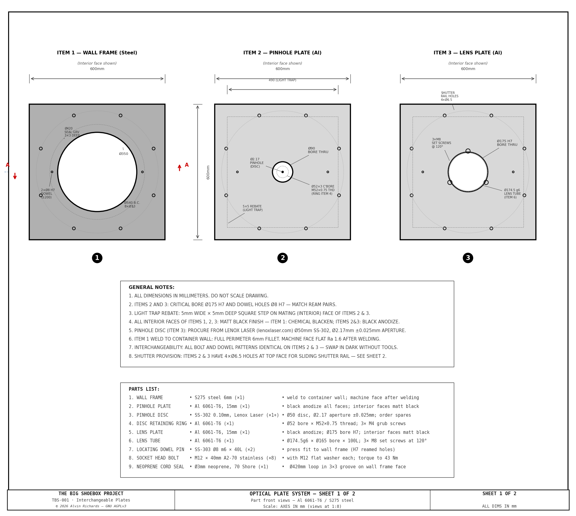
Both plates share the same bolt pattern (8× M12 on Ø540mm BC), dowel pin registration (2× Ø8mm), neoprene O-ring seal (Ø420mm groove), and 490mm square light-trap rebate — making them fully interchangeable.
3. Wall Frame (Item 1)
The wall frame is permanently welded to the container's far end wall. A Ø360mm hole is cut through the corrugated steel wall; the frame covers this opening and provides:
- Ø350mm circular aperture — clears the light path for both pinhole and lens operation
- 8× M12 tapped holes on a Ø540mm bolt circle — receives plate mounting bolts
- 2× Ø8mm dowel pin holes at ±200mm from center — registers each plate to the same optical axis
- Machined mating face — flat sealing surface for the neoprene O-ring
The frame is the only component that touches the container wall. All alignment references originate from it.
4. Pinhole Plate (Item 2)
The default plate for camera obscura operation:
- Ø90mm tapered bore on the exterior (scene) face — admits a wide cone of light
- Ø52mm × 3mm deep counterbore (M52×0.75 internal thread) on the interior (camera) face — seats the pinhole disc
- Ø50mm × 0.1mm SS-302 pinhole disc (Lenox Laser) — Ø2.17mm aperture (Rayleigh optimal for f=2,362mm, λ=550nm)
- Light-trap rebate — 490mm square, 5mm wide × 5mm deep step on the mating face prevents stray light leaking past the O-ring seal
The pinhole disc is clamped by an aluminum retaining ring (M52×0.75 thread) that screws into the counterbore over the disc, holding it flat against the seat; 3× M4 grub screws lock the ring. It unscrews so the disc can be cleaned or swapped without disturbing the plate. Procurement: Lenox Laser custom pinhole discs, specify SS-302 Ø50mm substrate, Ø2.17mm ±0.025mm aperture.
5. Lens Plate (Item 3)
The alternate plate for lens-based operation:
- Ø175mm H7 bore — precision-machined to accept the lens tube with an H7/g6 sliding fit (0.5mm diametral clearance)
- Ø174.5mm g6 lens tube — slides in the bore with ±40mm focus travel
- 3× M8 set screws at 120° — lock the tube at the desired focus position
- Ø165mm tube inner bore — clear passage for the lens assembly
- Focus positions: at 3.4m subject distance, lens principal plane is 1,400mm from the pinhole wall interior face; at 5.0m, retract to 1,604mm. Mark both positions with scribed lines on the tube.
The lens plate has the same bolt pattern, dowels, seal groove, and light-trap rebate as the pinhole plate.
6. Plate Changeover
To switch between pinhole and lens operation:
- Release 8× M12 bolts from inside the camera
- Withdraw the installed plate from the dark side
- Insert the alternate plate — dowel pins guide it into alignment
- Re-torque M12 bolts
No re-measurement or optical alignment is required. The dowel pins guarantee repeatable registration of the optical axis.
7. Sealing & Light Integrity
| Feature | Specification |
|---|---|
| O-ring seal | Ø420mm centerline, 3mm wide × 3mm deep groove, neoprene cord |
| Light-trap rebate | 490mm square, 5mm wide × 5mm deep step on mating face |
| Frame mating face | Machined flat, matt black finish |
| Plate mating face | Machined flat, matt black anodize |
The O-ring provides the primary light seal under bolt compression. The light-trap rebate provides a secondary labyrinth seal around the full perimeter — any light that passes the O-ring must navigate a 5mm step change before reaching the interior.
8. Engineering Drawings
Sheet 1 — Front Views
Front elevation of all three components at 1:8 scale, showing bolt patterns, apertures, dowel pin locations, seal grooves, and light-trap rebates.
Sheet 2 — Sections and Details
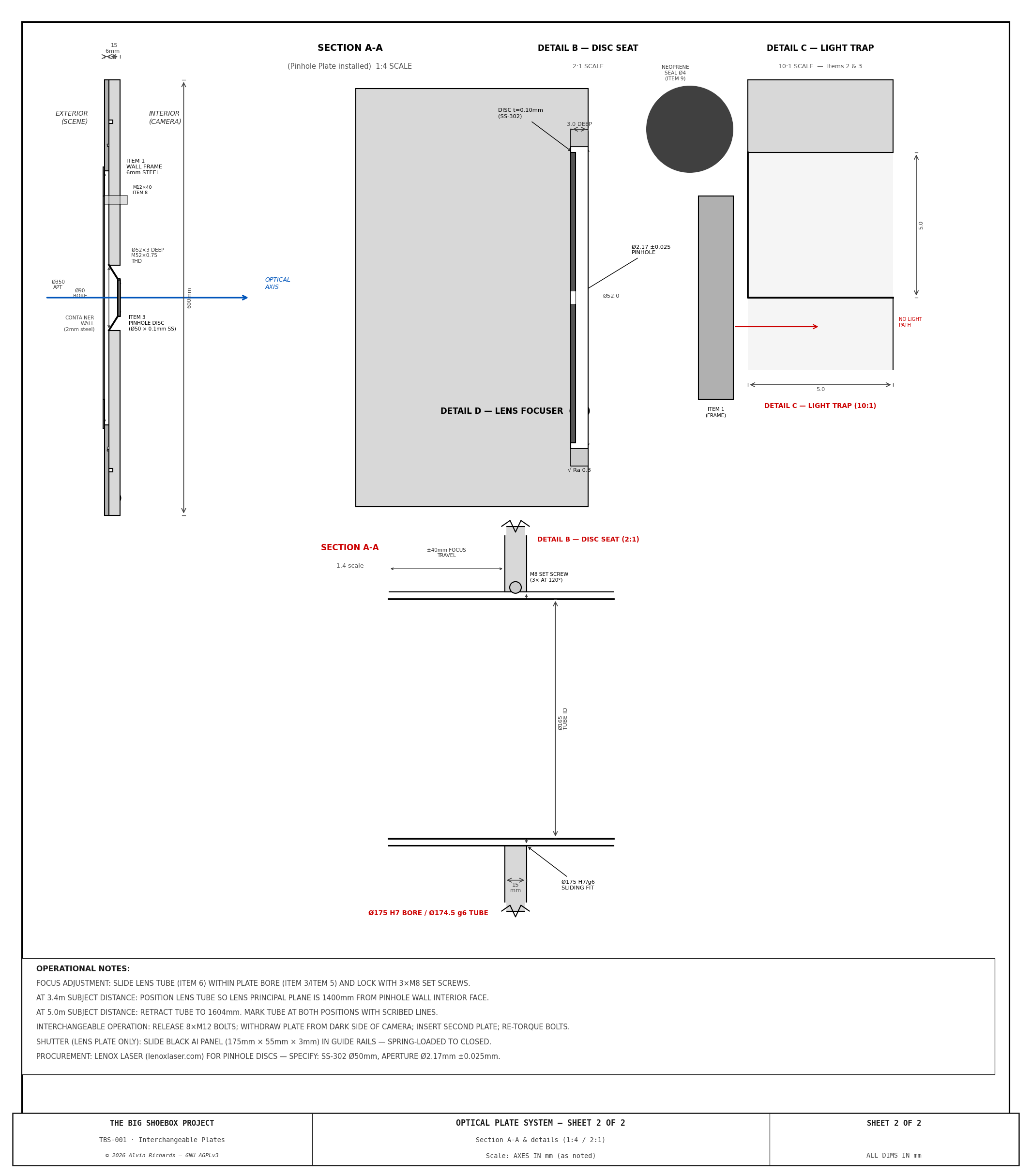
| View | Scale | Content |
|---|---|---|
| Section A-A | 1:4 | Cross-section through the full stack: container wall → frame → plate → bore |
| Detail B — Disc Seat | 2:1 | Pinhole disc counterbore, threaded retaining ring, and disc seating |
| Detail C — Light Trap | 10:1 | Light-trap rebate cross-section showing labyrinth seal path |
| Detail D — Lens Focuser | 1:2 | Lens tube in bore with H7/g6 fit, set screw locking, and focus travel |
9. Parts List
| Item | Spec | Qty | Source |
|---|---|---|---|
| 1 — Wall Frame | S275 steel 6mm (+1), 600 × 600mm | 1 | Weld to container wall; machine face after welding |
| 2 — Pinhole Plate | 6061-T6 Al, 600 × 600 × 15mm | 1 | Machined; matt black anodize; interior faces matt black |
| 3 — Lens Plate | 6061-T6 Al, 600 × 600 × 15mm | 1 | Machined; Ø175 H7 bore; interior faces matt black |
| 4 — Pinhole Disc | Ø50 × 0.1mm SS-302, Ø2.17mm aperture | 1 | Lenox Laser |
| 5 — Lens Tube | Ø174.5 g6 × Ø165 ID × 100mm, 6061-T6 | 1 | Machined; black anodize |
| 6 — Mounting Bolts | M12 × 40mm, A2 stainless | 8 | McMaster-Carr / Bolt Depot |
| 7 — Dowel Pins | Ø8 × 40mm, hardened | 2 | McMaster-Carr |
| 8 — O-ring Cord | Neoprene, 3mm Ø, ~1,320mm length (Ø420mm circle) | 1 | McMaster-Carr |
| 9 — Set Screws | M8 × 8mm, cup point, A2 stainless | 3 | McMaster-Carr / Bolt Depot |
| 10 — Shutter Panel | 175 × 55 × 3mm, black aluminum | 1 | Guide rails spring-loaded to closed |
| 11 — Disc Retaining Ring | Al 6061-T6, Ø52 bore × M52×0.75 thread, 3× M4 grub screws | 1 | Machined (local fab) — clamps the disc; unscrews for swap/clean |
10. See Also
- Tilt-Swing Front Board — spherical-pivot adapter that replaces the pinhole plate, adding ±5.3° tilt and swing adjustment
- Electrical Report — circuit assignments and wiring
- Engineering Diagrams — complete diagram index
11. Source References
- Lenox Laser — Custom Pinhole Apertures — pinhole disc procurement (SS-302, Ø50mm substrate).
- Rayleigh Criterion for Pinhole Cameras — optimal aperture formula d = 1.9√(fλ).
- ISO 286-2 — Limits and Fits — H7/g6 tolerance class for sliding fit bores.
- McMaster-Carr — fasteners, dowel pins, O-ring cord.