Plumbing Report¶
Two plumbing panels. The water-handling equipment is split across two panels: the Corridor Plumbing Panel (pumps P-01/P-02/P-03/P-05, accumulator ACC-01, pump-suction isolation valves — mounted in the IBC plumbing corridor) and the Pinhole Wall Filter Skid (the filter train + the tray-drain skid: tray-drain pump P-04, sample taps SV-01/SV-02, diverters DV-01/DV-02, the 3-stage Big Blue filter, and the recycle-spray damper ACC-02 — mounted on the pinhole wall). This report covers both.
Interactive 3D model¶
TBS-001 Water System Model by alvin91403 on Sketchfab
1. Purpose¶
The water-handling equipment mounts on two plumbing panels:
- The Corridor Plumbing Panel — an 18mm exterior-grade plywood board mounted vertically at the front (cargo-door-facing) mouth of the IBC plumbing corridor on the front-portal frame (270mm corridor width × 2,060mm tall). It carries the transfer pumps (P-01 Blue supply, P-02 Brown recycle, P-03 waste, P-05 Brown drain), the pressure accumulator (ACC-01), and the pump-suction isolation valves.
- The Pinhole Wall Filter Skid — the filter train + the tray-drain skid mounted on the pinhole wall: the tray-drain pump P-04, the skid-row sample tap (SV-02) and diverter (DV-02), the 3-stage Big Blue filter (F1/F2/F3), the filter-output sample tap (SV-01) and diverter (DV-01), and the recycle-spray damper (ACC-02).
Each panel concentrates its part of the system in one accessible location. The panels serve three functions:
- Structural mounting surface — provides a rigid, flat substrate for equipment that would otherwise require individual mounting brackets on the corrugated container walls.
- Plumbing coordination — all pump suction and discharge lines, filter connections, and valve positions are organized on one face, minimizing pipe runs and simplifying maintenance.
- Accessibility — the panel faces the open end of the container. The operator approaches from the right walkway and reaches into the 270mm corridor to access the valves (the pumps are switched at the EP — §3.2).
2. Panel Specifications¶
| Parameter | Value |
|---|---|
| Material | 18mm exterior-grade plywood (BC/ACX) — dry mounting board, not marine |
| Face dimensions | 270mm wide (Yd) × 2,060mm tall (Z) |
| Orientation | Vertical, perpendicular to sealed end wall |
| Bottom edge | Just above the walkway deck (clear of the spill line) |
| Top edge | Just below the container ceiling |
| Corridor width | 270mm (between near and far IBC columns) |
| Mounting | L-brackets to the front-portal frame uprights, 4 points |
| Finish | Sealed cut edges (exterior grade); white face for visibility |
The table above is the Corridor Plumbing Panel. The Pinhole Wall Filter Skid is the wet-end board mounted on the pinhole wall carrying the 3-stage filter train, the tray-drain skid row (P-04·SV-02·DV-02), the filter-output diverter DV-01 + the SV-01 sample tap, and the recycle-spray damper ACC-02 — see Water System Report §3 for its location and the spray-bar/chemistry-tap supply it feeds.
3. Equipment Layout¶
The Pinhole Wall Filter Skid carries the 3-stage filter train + the tray-drain skid row P-04·SV-02·DV-02 (§3.1); the Corridor Plumbing Panel carries the four corridor pumps (P-01/P-02/P-03/P-05) and the accumulator (§3.2–§3.3). Each panel has its own front-elevation drawing; the corridor backside (drain-riser spine + Circuit-C power) is a third sheet.
3.1 Pinhole Wall Filter Skid — Filter Train + Tray-Drain Row¶
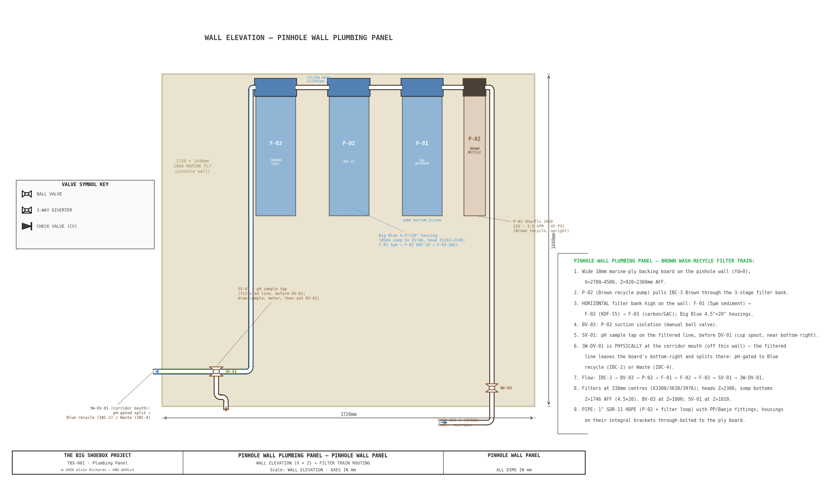
Three 4.5"×20" Big Blue filter housings in a horizontal bank mounted high on the pinhole wall — the heads (with the 1" NPT ports) pinned just below the ceiling, the sump bowls hanging below — so the walkway stays clear and the operator reaches up to service them. The tray drain feeds the filters: tray sump → P-04 → SV-02 sample tap → 3W-DV-02 → F-01 (5μm sediment) → F-02 (KDF-55) → F-03 (carbon) → SV-01 sample tap → 3W-DV-01. The tray-drain skid row (P-04·SV-02·DV-02) sits directly under the filters; ACC-02 (the recycle-spray damper for P-02) is at the panel's center-bottom.
Pinhole Wall Filter Skid — Front elevation: tray-drain skid row (P-04·SV-02·DV-02), 3-stage filter bank, SV-01 + DV-01, and ACC-02
| Stage | Media | Housing |
|---|---|---|
| F-01 (sediment) | 5μm MPP melt-blown polypropylene | 4.5"×20" Big Blue |
| F-02 (heavy metal) | KDF-55 heavy-metal removal | 4.5"×20" Big Blue |
| F-03 (carbon) | CTO coconut-shell activated carbon | 4.5"×20" Big Blue |
Each housing has 1" NPT inlet and outlet on the head; the heads sit on a common line and the sumps hang below, each housing carried on its own Pentair 150061 bracket. Inter-housing piping connects F-01 OUT → F-02 IN and F-02 OUT → F-03 IN using 1" PVC pipe (threaded at the filter ports) with 90° elbows routed outside the housing bodies. Each housing machine-screws through its own mounting-hole ears (on 25mm plywood-offcut standoff blocks) into back-face pronged tee-nuts in the 18mm ply backing, giving sump-bowl clearance — no custom bracket (see the DETAIL — HOUSING MOUNT (section) inset on the panel elevation above).
Head clearance: the 20" sumps hang ~250mm lower than a 10" housing would — to roughly shoulder height for the 1.75m scale operator — in exchange for ~2× the interval between cartridge changes. If the lower bank proves an operational nuisance, the housings swap directly to 4.5"×10" (same heads and ports, shorter sumps, half the interval).
Replacement interval (4.5"×20" cartridges — roughly 2× the 10" life):
| Stage | Cartridge | Removes | Replace every |
|---|---|---|---|
| F-01 | 5μm MPP sediment | Gross sediment, fiber lint, Prussian blue particles | ~50 prints |
| F-02 | KDF-55 | Dissolved iron from ferricyanide wash water | ~60 prints |
| F-03 | CTO carbon block | Residual organics, color | ~40 prints |
Alternative: A single 3-stage combo unit (e.g. Purcooflow WHF2045B302 or iSpring WGB32B) with 4.5"×20" cartridges eliminates the inter-housing plumbing and the separate frame — one integrated bracket, 1" NPT inlet/outlet, a single 1/2"→1" bushing at the DV-02 recycle feed. See Water System Report §3.2 for sizing rationale.
3.2 Corridor Plumbing Panel — Pump Zone¶
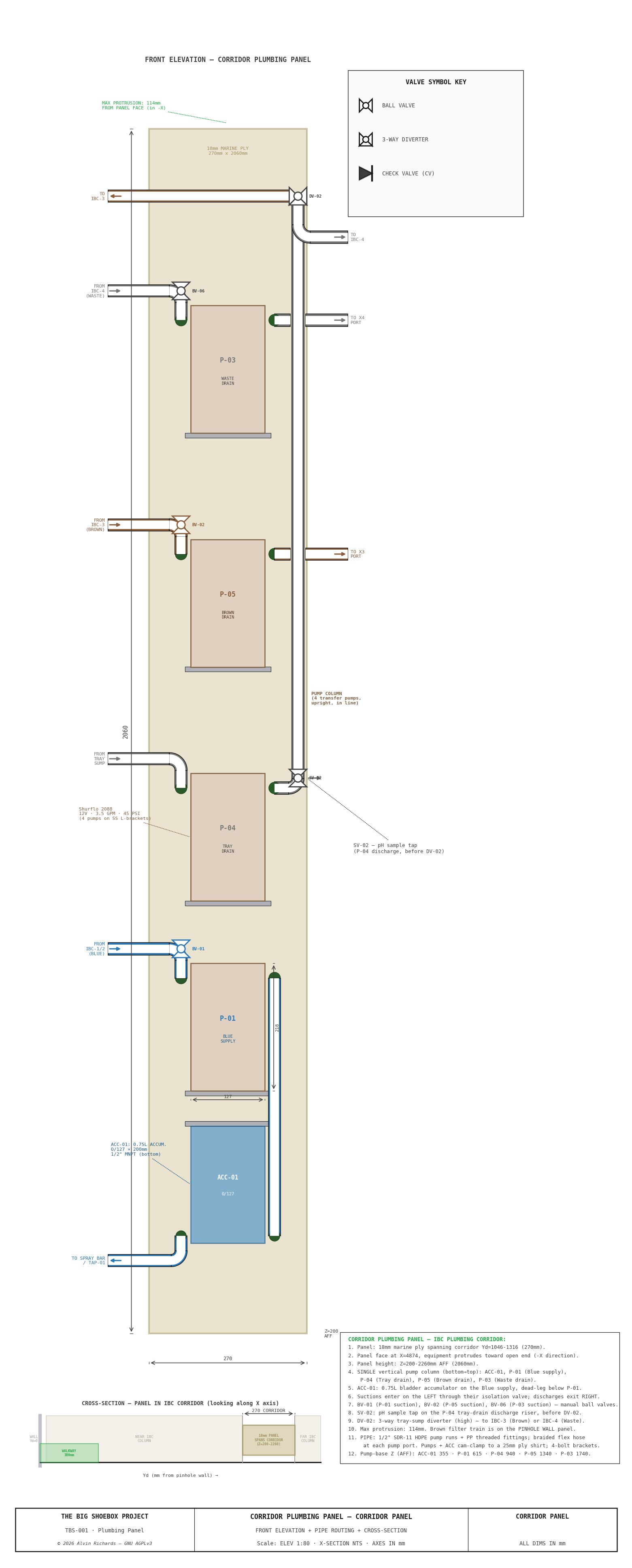
Four Shurflo 2088 pumps mount on the Corridor panel (P-04, the tray-drain pump, lives on the Pinhole Wall filter skid, §3.1). The accumulator ACC-01 sits at the column foot (§3.3).
| Pump | Circuit | Function |
|---|---|---|
| P-01 | Blue | Clean water supply to spray bar (via ACC-01) |
| P-02 | Brown | Recycle spray — pulls the clean IBC-3 buffer → ACC-02 → BV-05 → spray bar |
| P-03 | Black | Waste evacuation (IBC-4 residual → external drain X4) |
| P-05 | Brown | Brown drain-out (IBC-3 → external drain X3) |
All pumps are identical Shurflo 2088-554-144 units: 12VDC, 3.5 GPM, 45 PSI, self-priming diaphragm. Vertical mount, ports at the head, 127mm body width × 216mm body height × ~114mm protrusion. Each mounts on a stainless 4-bolt bracket through the plywood. They sit in a single vertical column in the 270mm corridor; P-01 and P-02 draw from the near IBC column, P-03 and P-05 from the far column.
Pump electrical — Circuit C (one at a time)¶
All five pumps run from the single Circuit C feed (12V DC, 15A fuse, 14 AWG from the Blue Sea fuse block — see Electrical Report §7.2–7.3). Circuit C is switched at a master pump switch on the Electrical Panel (EP) — one IP-rated cutoff for the whole pump circuit, upstream of everything — then runs the ceiling trunk to a 12V DC distribution block (positive + shared negative bus) on the rear of this panel; from it a short 16 AWG branch feeds each pump directly.
| Item | Spec |
|---|---|
| Feed | Circuit C, 14 AWG, 15A fuse (one feed for all five pumps) |
| Master switch | 1 × IP-rated sealed rocker/disconnect (12V, 16A), mounted on the EP — single cutoff upstream of the whole circuit; no per-pump switches (each Shurflo runs on its internal pressure switch) |
| Distribution | 12V DC + / − bus block on the rear of the plumbing panel, fed from the EP master switch |
| Branches | 16 AWG, ~0.5–1m, block → pump, curved-elbow conduit (7.5A / 90W per pump) |
The pumps are operated one at a time: with the EP master switch on, the operator opens the relevant ball valves for the current task (others closed), and that pump's Shurflo internal demand/pressure switch then runs it on demand. The 15A fuse covers a single pump with margin; simultaneous running is not intended. The distribution block sits above the spill line, IP-rated and sealed, with drip loops, per the wet-zone rules in Electrical Report §7.5; the master switch is on the EP, clear of the wet zone.
Corridor Plumbing Panel — Front elevation: the four transfer pumps (P-01/P-02/P-03/P-05), ACC-01, and full pipe routing
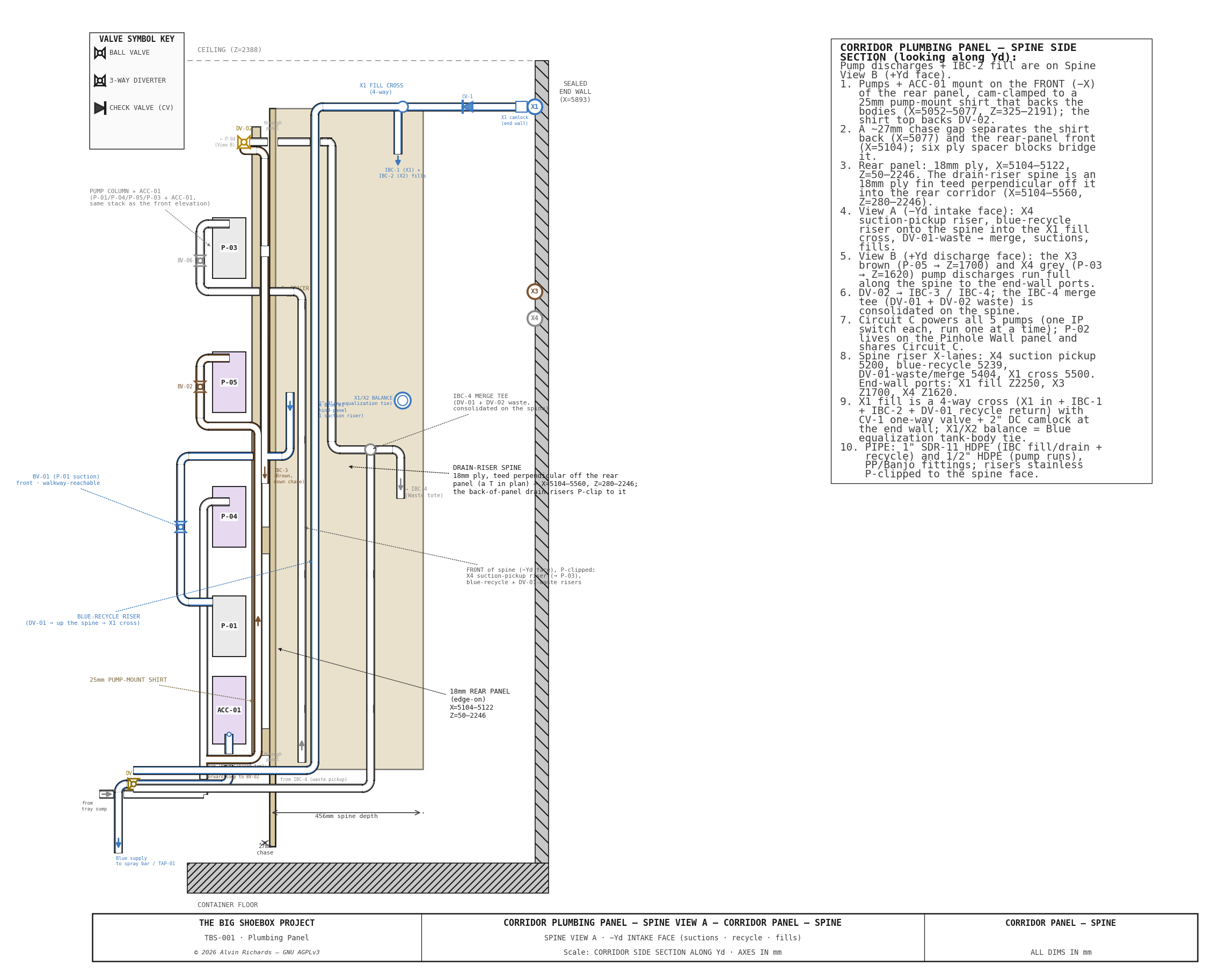
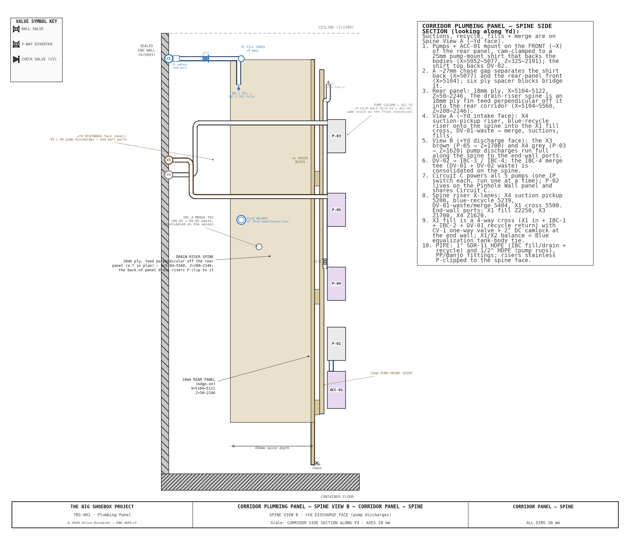
Spine side-sections (corridor side section) — two sheets, opposite faces of the drain-riser spine (18mm ply teed off the panel). Pumps mount on the front face; the drain runs hang on the spine in the corridor gap clear of both tote columns; the Circuit-C pump-power distribution feeds all five pumps. P-04 lives on the Pinhole Wall filter skid and shares Circuit C. The two views share all structure + fittings as landmarks; each face's own pipe runs appear on its own sheet. (Spine views A/B still show the pre‑Phase‑2 corridor tray‑drain routing — pending the topology update; see §8.1.)
Spine View A — intake face: suctions (BV-01 Blue, tray sump, IBC-3),
the DV-01 blue-recycle riser climbing the spine into the X1 fill cross, the
DV-01-waste → IBC-4 merge, and the IBC-1 / Blue-supply fills.
Spine View B — discharge face (a mirror of A): the X3 brown (P-05) and X4
gray (P-03) pump discharges running full along the spine to the sealed end-wall
ports, the P-01 → ACC drop, the P-04 discharge through SV-02, and the IBC-2 fill.
3.3 Accumulator¶
| Parameter | Value |
|---|---|
| Model | SeaFlo SFAT-075-125-01, 0.75L (23.5 oz) |
| Dimensions | 127mm OD × 200mm length |
| Position | Corridor panel, at the column foot (below P-01 — the P-01/ACC order was swapped to drop the accumulator to the base) |
| Port | 1/2" NPT, bottom |
| Function | Smooths P-01 pump cycling, maintains pressure when the pump is off |
ACC-01 sits inline on the Blue discharge path between the P-01 outlet and the spray-bar supply trunk (BV-05). The accumulator's air bladder absorbs pressure pulsations from the diaphragm pump, providing steady flow to the spray bar.
4. Valves¶
4.1 Ball Valves (Isolation)¶
| Valve | Size | Panel | Function |
|---|---|---|---|
| BV-01 | 1/2" | Corridor | P-01 (Blue supply) suction isolation |
| BV-02 | 1/2" | Corridor | P-05 (Brown drain) suction isolation |
| BV-03 | 1/2" | Corridor | P-02 (Brown recycle) suction isolation |
| BV-04 | 1/2" | supply | TAP-01 chemistry-tap isolation |
| BV-05a | 1/2" | supply | Spray Blue/Brown SELECTOR — 1/2″ 3-way divert (same valve as DV-01/02) |
| BV-05b | 1/2" | spray bar | Spray-bar ON/OFF — 1/2″ 2-way ball valve |
| BV-06 | 1/2" | Corridor | P-03 (waste evacuation) suction isolation |
BV-01/BV-02/BV-03/BV-06 are the Corridor panel pump-suction isolation valves; BV-04 isolates the TAP-01 chemistry tap. These five are 1/2" Banjo V050FP quarter-turn 2-way ball valves.
BV-05 is the spray SELECTOR — split into two 1/2″ valves rather than one 3-way L-port. Both the Blue (fresh) and Brown (recycle) lines converge here, and the operator needs three states: Blue → spray, Brown → spray, and off. A single 3-way that both selects and shuts off is only available as an L-port in 3/4″ (Banjo V075BL, $72.88 — needing reducers to the 1/2″ lines and a verified OFF detent, since some L-ports cross-connect the two inlets at the 4th quarter-turn instead). So the design uses two plain 1/2″ valves instead:
- BV-05a — Blue/Brown selector: a 1/2″ 3-way divert valve (the same US Plastic #22365 used for the diverters), plumbed 2 inlets → 1 outlet, set at the panel to pick Blue or Brown.
- BV-05b — spray on/off: a 1/2″ 2-way ball valve at the spray-bar feed, where the operator controls flow during the wash pass.
This keeps everything 1/2″ (no reducers), avoids the L-port OFF-detent risk, runs ~$37 cheaper than the 3/4″ L-port, and puts the on/off where the operator's hand is. (The five 1/2″ 2-way isolation valves also re-sourced to Grainger 803HZ1 at $24.14, down from $44.27.)
4.2 Diverter Valves (3-Way)¶
| Valve | Size | Position | Function |
|---|---|---|---|
| 3W-DV-01 | 1" FNPT | After the filter train + SV-01 sample tap | Routes filtered water to recycle (IBC-3 Brown buffer) or Black (IBC-4 waste) based on the SV-01 pH reading |
| 3W-DV-02 | 1/2" FNPT | Skid row, after SV-02 | Routes the tray-drain water into the filters (F-01, recycle) or straight to Black (IBC-4 waste) based on operator judgment |
3W-DV-02 is the operator judgment valve: set to recycle (default) — into the filters for cleaning — for normal rinse water, switch to Black for heavy contamination events.
3W-DV-01 is the pH-gated valve: draw a sample at SV-01 (below) and meter it — if filtered water reads pH 6–7, route to recycle (IBC-3 Brown buffer, which P-02 later sprays back); if pH >7.5 or discolored, route to Black (IBC-4).
4.3 Check Valves¶
| Valve | Size | Position | Function |
|---|---|---|---|
| CV-1 | 1" NPT | X1 bulkhead fill line | Prevents backflow from the Blue totes to the external fill port |
** Check Value CV-1** The Shurflo 2088 pumps have integral check valves. CV-1 guards the single gravity (non-pumped) path, the X1 fresh-fill. Installed in the IBC zone, not on a panel.
4.4 Sample Tap (SV-01)¶
| Valve | Size | Panel | Function |
|---|---|---|---|
| SV-01 | 1/2" | Pinhole Wall | Filtered-Brown line (F-03 outlet → 3W-DV-01) — pH sample before the Blue/Black diversion |
| SV-02 | 1/2" | Pinhole Wall (skid row) | P-04 tray-drain discharge (→ 3W-DV-02) — pH sample before the recycle/waste diversion |
The filter output has no usable sampling point without SV-01 — a capped tee cannot be drawn from. SV-01 is a 1/2" PP quarter-turn ball valve (same Banjo family as the BV isolation valves) on a 1"×1/2" reducing branch tee, with a short downturned hose-barb spout. It sits on the panel face above the spill line, spout pointing toward the operator so a cup fits beneath it from the right walkway.
Use: run P-04 to pressurize the filtered line, crack SV-01 to catch ~50 ml in a cup, close it, read pH on the meter, then set 3W-DV-01 to recycle-return (pH 6–7) or Black-waste (pH drift / discolored).
5. Pipe Specifications¶
| Run | Schedule | Nominal Size | OD (mm) | Material | Notes |
|---|---|---|---|---|---|
| Pump suction/discharge | Sch 40 | 1/2" | 21 | PVC Sch 40 | Matches Shurflo 2088 port thread |
| DV-02 outputs | Sch 40 | 1/2" | 21 | PVC Sch 40 | To F-01 (recycle) or IBC-4 (waste) |
| DV-01 outputs | Sch 40 | 1/2" | 21 | PVC Sch 40 | To Blue IBC-2 or Black IBC-4 |
| Filter inter-stage | Sch 40 | 1" | 33 | PVC Sch 40 | Matches Big Blue 1" NPT ports |
| Filter outlet → DV-01 | Sch 40 | 1" | 33 | PVC Sch 40 | Gravity flow, lower restriction |
| IBC fill/drain (internal) | Sch 40 | 1" | 33 | PVC Sch 40 | IBC valve to corridor |
| IBC fill/drain (external bulkhead) | Sch 40 | 2" | — | PP (EPDM gaskets) | Bulkhead unions with camlock |
| Spray bar flex hose | — | 1/2" | — | Reinforced braided PVC | ~4m coiled, BV-05 to beam center feed |
All pump-driven internal runs use 1/2" pipe, matching the Shurflo 2088 pump ports (1/2"-14 male parallel thread). This eliminates reducer fittings at pump connections. The only reducer is a single 1/2"→1" bushing at the filter skid inlet (P-02 output to F-01 input).
5.1 Joint Convention¶
Pipe joints are solvent-weld (slip socket) by default — the run is glued PVC. Threaded (NPT) is used only where a run lands on a hard component that must be removable for service: pumps, filter housings, valves, check valves, tank bulkheads, sample taps, and the accumulator. Each such interface uses a slip×NPT transition adapter (a male adapter glued into the run, threaded into the component's port). This keeps the run cheap and leak-free while every component stays unthreadable for maintenance.
Classifying the current BOM by this rule:
| Category | Connection | Parts |
|---|---|---|
| Run joints — SLIP | glued PVC socket | tees, elbows, cross, couplings, pipe |
| Component interfaces — THREADED | NPT (via slip×NPT adapter) | ball/diverter/check valves, camlocks, tank bulkheads, pump & filter ports, sample taps, accumulator |
Applying this convention (a) resolved 2026-07-27: the run material is PVC Sch-40 (see §5.2 — the §5 table is updated). Still open (see TODO): (b) the 1" run tees/elbows now carried as threaded Banjo FRPP move to PVC slip, and (c) a slip×NPT male adapter is added at each component interface (currently absent from the BOM). The valves, camlocks, bulkheads, check valve, and pump/filter ports stay threaded.
5.2 Material: PVC Schedule 40 (justification)¶
The run pipe is PVC Sch-40, solvent-welded. PVC is chosen over HDPE because for this service the deciding factors are buildability and cost, not the toughness where HDPE leads:
- Joining — decisive for a hand-built system. PVC solvent-welds with primer + cement and hand tools; HDPE cannot be glued — it needs heat-fusion equipment or bulkier, costlier mechanical/barbed fittings. Solvent-weld is what makes the §5.1 slip convention practical.
- Pressure. At the 45 PSI Shurflo 2088 service, Sch-40 (½" ≈ 600 PSI @ 73 °F) carries a ~13× margin — a non-issue for either material.
- Chemistry. Both are fully compatible with the dilute cyanotype wash (potassium ferricyanide, ferric ammonium oxalate, citric acid) — no advantage either way.
- Cost & availability. PVC pipe, fittings, and valves are the cheapest option and stocked everywhere (Home Depot); HDPE fittings are scarcer and pricier.
The trade accepted: HDPE's edge is toughness — impact, vibration, and freeze resistance for a transported system. Both risks are mitigated operationally: the system is drained for transport (no freeze-crack, less vibration mass) and every pump is de-coupled from the rigid run on both ports — a braided ½" flex jumper on the suction and discharge of all five pumps (P-04's suction is the 1" tray-drain hose), barb-coupled and SS-clamped, so pump vibration can't fatigue-crack a solvent-weld joint; rigid runs are clipped at close intervals. Keep runs off the sunniest wall face — PVC softens near 60 °C, though it retains > 200 PSI hot, far above service. (If a future deployment must travel wet or in freezing conditions, PEX is the tougher DIY alternative.)
5.3 Pump-run supports¶
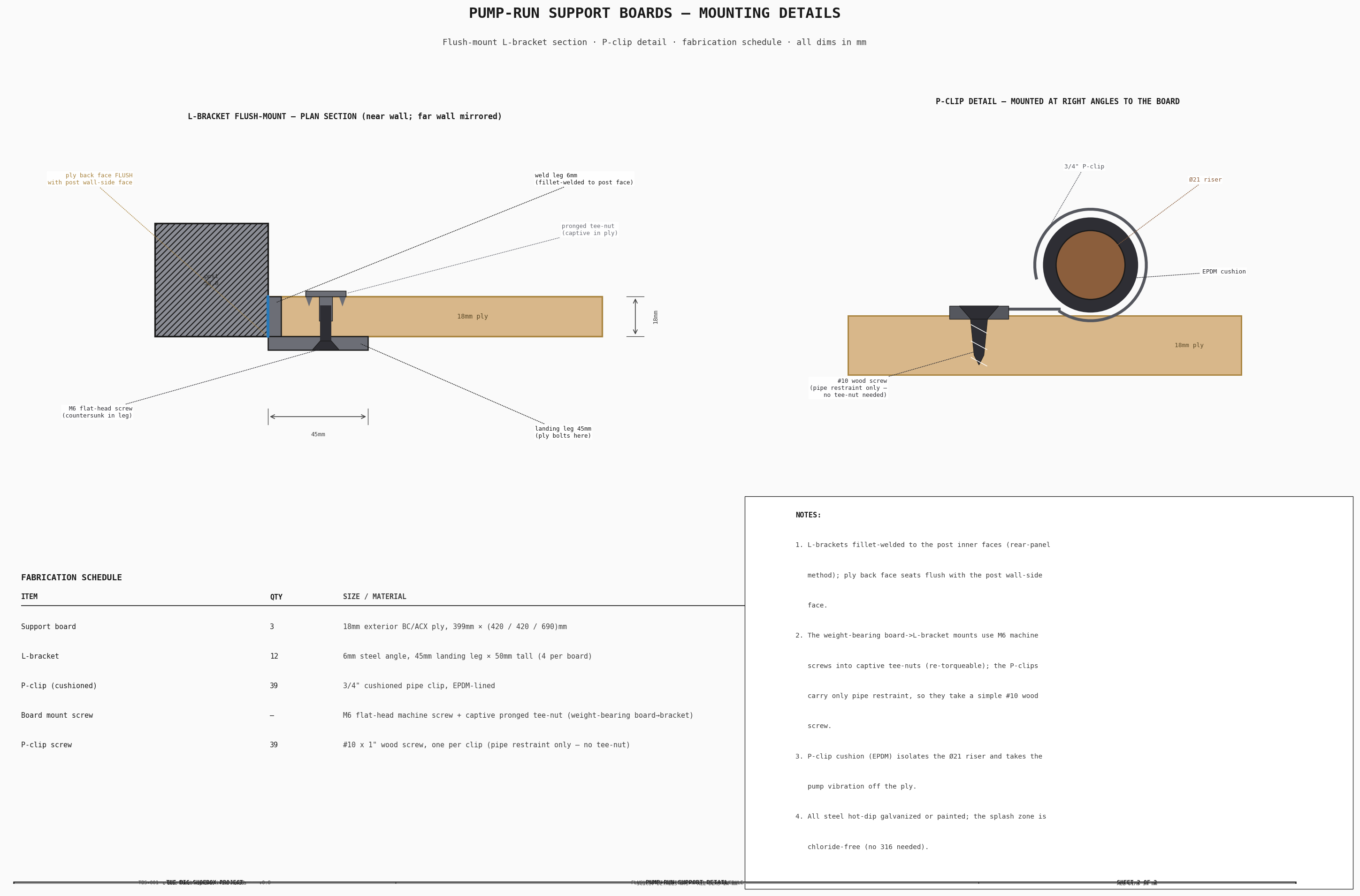
The corridor pump risers and the back-of-panel drain runs cantilever off the pump ports and tote taps, so each is backed and clamped rather than left hanging on its solvent-weld joints. The method mirrors the rear panel: 18mm exterior-ply boards recessed flush into the window between the IBC-frame front and rear side-posts, carried on welded steel L-brackets (one leg welded to each post inner face, the ply bolted to the landing leg), with the runs held to the board face by cushioned P-clips.
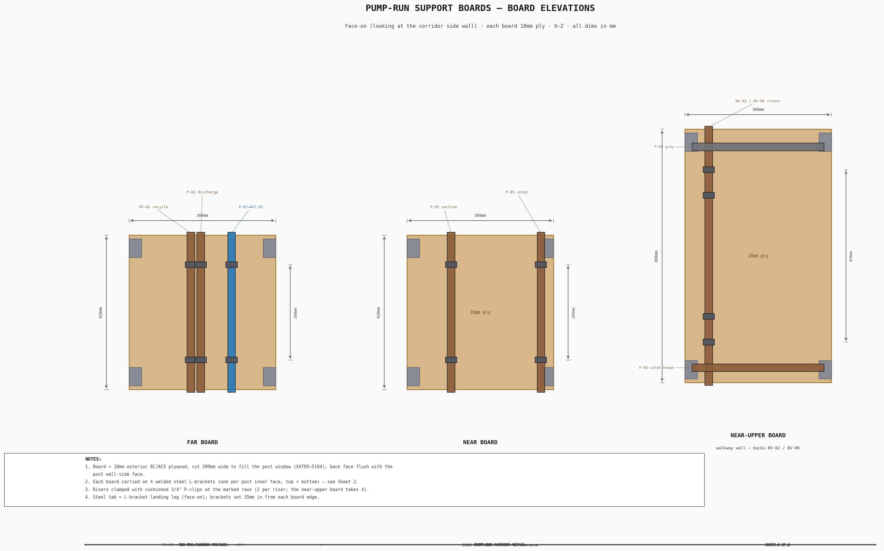
- Corridor side walls — one board per wall. The far (film-plane) side backs the DV-01 recycle, P-02 discharge, and P-01→ACC-01 risers; the near side carries the P-02 suction riser (with BV-03) on a lower board and BV-02 / BV-06 (P-05 / P-03 suction) on an upper board. Each riser is pulled flush onto its board plane, and the DV-01 recycle line is re-routed off IBC-3 and down the far board before turning into DV-01.
- Drain-riser spine — the three gray/brown waste risers clamp to the spine's near face; the P-05→X3 and P-03→X4 lines running along the spine's far face toward the end wall clamp to it too.
- Filter skid — the vertical skid runs (DV-02→F1, tray-sump→P-04, F3→SV-01) are pulled onto the backing panel and clamped, with the ACC-02 / SV-01 / DV-02-row horizontals held to the panel.
The near-board ball valves (BV-02 / BV-06) turn their handles into the open corridor and sit on forward loops at the walkway edge, so they clear the panel and stay reachable. Hardware: 3 side boards (cut from the corridor ply sheet — no added ply), 12 welded L-brackets, and 39 cushioned 3/4" P-clips (§Parts).
6. Flow Paths¶
6.1 Blue System — Clean Water Supply¶
IBC-1/IBC-2 → BV-01 → P-01 → ACC-01 → BV-05 → spray bar
P-01 draws from the Blue IBC manifold (two IBCs plumbed in parallel via 1" HDPE with isolation valves), pressurizes through ACC-01 (0.75L accumulator), and delivers to BV-05 on the spray-bar feed. A 4m flexible hose connects BV-05 to the spray bar center feed bulkhead.
6.2 Brown System — Used Water Recycling¶
Tray sump → P-04 → SV-02 sample → 3W-DV-02 → 1/2"→1" reducer → F-01 → F-02 → F-03
  → SV-01 sample tap → 3W-DV-01 → IBC-3 recycle (if pH 6–7) or IBC-4 waste (if pH drift)
IBC-3 → P-02 → ACC-02 → BV-05 → spray bar   (recycle spray)
P-04 lifts drain water from the processing tray sump (~900mm head) and, via 3W-DV-02, sends it into the 3-stage filter train. After filtering, the operator draws a sample at SV-01, checks pH, and sets 3W-DV-01 to route either to recycle (IBC-3 Brown buffer) or to Waste (IBC-4). P-02 then recirculates the clean IBC-3 buffer to the spray bar (via ACC-02 and BV-05) — the recycle-spray loop.
6.3 Black System — Waste Containment¶
3W-DV-01 reject → IBC-4
3W-DV-02 contaminated → IBC-4
IBC-4 → P-03 → external drain port X4 (gravity + pump assist)
P-03 is dedicated to waste evacuation. IBC-4 gravity-drains through external port X4 down to approximately 120L residual; P-03 pumps the residual below the gravity drain height to a disposal tanker.
7. Mounting and Structure¶
7.1 Plumbing Panel Mounting¶
The plywood panel is secured to the IBC restraint front-portal frame uprights (at the corridor mouth) at four points using L-brackets with M10 bolts. The frame provides rigid lateral restraint — the panel does not contact the container walls directly.
7.2 Filter Skid Mounting¶
The filter skid uses no separate frame: each housing is carried on its own Pentair 150061 zinc single-housing bracket machine-screwed to the 18mm plywood backing (this replaced the earlier welded slotted-angle frame — purpose-built, −$85). The mount provides:
- Rigid support for the ~5kg weight of each filled filter housing
- 18mm plywood backing board with back-face pronged tee-nuts for the housing machine-screws (a re-torqueable joint, serviceable without stripping the ply)
Each filter housing mounts through its own mounting-hole ears — Big Blue heads are pre-drilled for wall mounting — with 5/16"-18 zinc machine screws into back-face pronged tee-nuts in the 18mm plywood backing (no custom bracket; #30 — a re-torqueable machine-screw joint, not wood/lag screws). 25mm plywood-offcut standoff blocks behind each ear space the housing off the ply so the sump bowl hangs free and clears for cartridge changes. Two machine screws per housing.
7.3 Pump Mounting¶
Each Shurflo 2088 mounts on a stainless steel 4-bolt bracket (Shurflo OEM accessory). The bracket screws through the plywood panel. Pump body orientation is vertical with ports at the head (top), facing left and right. This orientation minimizes the footprint on the 270mm-wide panel and allows gravity to assist with priming.
7.4 Panel Protrusion Envelope¶
| Component | Protrusion from panel face (-X) |
|---|---|
| Pump body (Shurflo 2088) | 114mm |
| Filter housing (Big Blue 4.5"×20") | 130mm |
| Accumulator (ACC-01) | 127mm |
| Pipe fittings + valves | ~50mm |
The maximum protrusion is 130mm (filter housings). Combined with the 18mm panel thickness, the total X footprint is 148mm. There is a 653mm clear between the walkway and the nearest protruding component.
8. Pipe Routing Conventions¶
All piping on the plumbing panel follows the parallel-wall drawing convention used throughout TBS-001 engineering diagrams:
- Blue pipes — front layer (closest to viewer/operator)
- Brown pipes — middle layer
- Black/waste pipes — rear layer (closest to panel)
Pipe crossings use the gap-break method (rear pipe broken at crossing) for pipes of different system colors, and the bridge-arc method for same-color crossings.
Pipes enter and exit the panel zone at the left and right panel edges: - Left edge (near wall side) — Blue IBC suction, Blue discharge riser to pinhole wall - Right edge (far wall side) — Brown/Waste IBC connections, external drain routing
8.1 Corridor ↔ pinhole-wall ribbon (under the right walkway)¶
The four lines that connect the corridor equipment to the pinhole-wall skid — P-02 → ACC-02 (recycle spray), the DV-02 waste → IBC-4, the filtered return (SV-01 → DV-01), and the Blue supply trunk → TAP-01/spray bar — run together as a flat ribbon in the otherwise-dead space under the right-walkway grate, in the clear channel between the two walkway long beams (hugged to the outer/IBC edge, clear of the print zone). The lanes ride flush against the grate underside so the whole over-tray run clears the spray-bar carriage beneath it, and the two middle lanes alternate (Blue trunk / Brown sump) so the blue and brown lines never cross. This replaces routing them through the congested tray↔IBC gap.
At the first cantilever (nearest the pinhole wall) each line loops up over the
cantilever — then returns to the flush ribbon
height. Rather than dipping under the walkway support beam (which would foul the
spray carriage), each line crosses the outer long beam through an open-top notch
and drops the tray-edge slot — clear of the carriage travel — into the corridor,
where it rises to its equipment connection. The pump-suction lines carry their own
service turns (P-04's sump pickup rises straight out of the widened sump well and
elbows flat into the ribbon lane at flush height — no over-deck loop; DV-01's filtered
return makes a square 90° turn into the diverter's IN port). The ribbon is carried by four welded steel cross-braces between the walkway
bearers, with the lines clipped to them. The full set of cross-sections — routing
envelope, clearances, and the beam notch — is in
Walkway Pipe Routing; routing is verified
collision-free by src/models/check_interference.py (the ribbon is a sanctioned
exception to the processing-tray exclusion zone — it runs above the tray rim, under
the grate).
9. Parts List¶
The panel-mounted equipment for each plumbing panel is listed below — generated from the parts registry (firm low–high bands, April-2026 indicative basis). The full water-system BOM (pipe, fittings, IBC totes, external bulkhead ports, wiring, consumables) is in the Water System Report §Parts-List; the panel ply/backing and mounting hardware are sourced there and in the IBC stacking frame line.
9.1 Corridor Plumbing Panel¶
| Item | Spec | Qty | Supplier | Est. cost |
|---|---|---|---|---|
| Shurflo 2088-554-144 pump (×5 — P-01 Blue supply / P-02 Brown recycle-spray / P-03 waste evac / P-04 tray drain / P-05 Brown drain) (B00C1M6B1C) | 12VDC, 3.5 GPM, 45 PSI, 1/2" NPSM ports; 5 identical pumps, one per water-system duty (P-01..P-05). 2026-07-27: consolidated from 5 lines; firm $100 ea (Amazon B00C1M6B1C) | 5 ea | Amazon / Fresh Water Systems | $500 |
| SeaFlo accumulator (0.75 L) (SFAT-075-125-01) | 0.75 L, 125 PSI, 1/2" MNPT | 2 ea | Amazon | $72 |
| Corridor plumbing-panel ply (23/32" exterior) (303564747) | 4×8 ft 23/32" (18mm) RTD Southern Yellow Pine exterior sheathing — rear backing board + drain-riser spine + 3× pump-run side support boards (far + near-lower ~399×420, near-upper ~399×690, #29, cut from the sheet leftover — ~0.62 m² of a 2.97 m² sheet) + spacer offcuts. STANDARD exterior per project rule. Firm $29.30 (Home Depot 2026-07-23). Seal cut edges. | 1 sheet | Home Depot | $29 |
| Pump-mount shirt ply (23/32" exterior) (303564747) | 4×8 ft 23/32" (18mm) RTD Southern Yellow Pine exterior sheathing — pump-mount shirt (~610×1650 cut) behind P-01..P-05 + 6× spacer blocks. Same SKU as ply-18; 5× Shurflo 2088 (~6.5 kg total) need no more than 3/4". STANDARD exterior per project rule. Firm $29.30 (Home Depot 2026-07-23). May nest with ply-18 in one sheet at cut — carried separate for margin. Double-layer locally if extra pump-rail stiffness wanted. | 1 sheet | Home Depot | $29 |
| 6× steel angle brackets (corridor panel → IBC uprights) | L-brackets fixing the corridor plumbing panel to the IBC-frame back uprights — TEK-screwed to the post (J8, 2× #14 self-drillers per bracket — no weld, bolt-on to the pre-painted frame), rear panel fastened J4 (M8 into captive tee-nut), per ibc-stacking-report §3.5. Price est. | 6 ea | Home Depot | $15–$39 |
| Corridor panel mount fasteners (shirt-to-panel screws + lag bolts) | Shirt-to-panel screws + lag bolts landing the brackets into the panel/uprights. Price est. | 1 lot | Home Depot | $10–$11 |
| 36× #14 self-drilling TEK screws (bracket → post, J8/J9) | #14 × 1in HWH self-drilling TEK screw, #4/5 point (drills the ~6–8mm steel-to-steel: angle leg + the 3mm RHS post wall), 410 SS for the damp container. Attach the corridor-panel L-brackets (J8, 2×6=12) + the side-panel pipe-run L-brackets (J9, 2×12=24) to the IBC posts — NO weld, so the brackets bolt onto a pre-painted frame with no hot work. Price est. per-ea (sold in 100-boxes). | 36 ea | Home Depot / McMaster-Carr | $11–$20 |
| 12× steel L-brackets (side-panel pipe-run boards) + 4 skid standoff clamps | 12× steel L-brackets TEK-screwed to the IBC side-post inner faces (2 per post × 3 side-panel boards: far, near-lower, near-upper) — the side-wall boards carry the PIPE runs (P-clips), NOT pumps; the boards bolt to the landing legs (rear-panel method); + 4 short standoff brackets carrying the forward SV-01/DV-02 skid lines. Cut from 1×1×1/8 steel angle offcuts — attached J9 (2× #14 self-drillers per bracket, no weld), boards fastened J5 (¼-20 into captive tee-nut), per ibc-stacking-report §3.5. MATERIAL est.; FAB (cut) = shop quote (material-now rule). (Registry key kept as 'pump-support-brackets' for cost continuity; they support the pump-run PIPING.) | 1 lot | Metal Supermarkets / Home Depot | $12–$24 |
| 39× cushioned pipe P-clips (3/4" pipe) | Cushioned (rubber-lined) pipe P-clips securing the pump risers/runs to the ply support boards + spine + skid panel (#29): corridor side boards 17 (far 6 + near-lower 4 + near-upper 7), drain-riser spine 10 (6 riser + 4 far-side X-port lines), filter-skid 12 (6 risers + 6 runs) = 39. Sized for OD21 (3/4") PVC. Zinc + EPDM cushion. Price est. — firm at blueprint. | 39 ea | Home Depot / McMaster-Carr | $21–$37 |
| Banjo V050FP ball valve 1/2" FNPT (803HZ1) | PP full-port quarter-turn 2-way; pump-suction isolation BV-01 (P-01), BV-02 (P-05), BV-06 (P-03). Grainger firm $24.14 (checked 2026-08-07; was US Plastic $44.27). | 3 ea | Grainger | $72 |
| 3-way diverter valve 1/2" FNPT (22365) | L/T-port PVC-compatible; 3W-DV-02 (tray drain) + BV-05a (spray Blue/Brown SELECTOR — 2 inlets Blue+Brown → 1 outlet to BV-05b on/off). Same valve as the diverters. | 2 ea | US Plastic Corp | $48 |
| pH sample tap (SV-02) — 1/2" PP ball valve + barb spout + branch tee (36903) | pH sample on the P-04 tray-drain discharge, before 3W-DV-02; same build/SKU as SV-01 (US Plastic 36903 $19.26 — priced under SV-01; applied to SV-02 as the identical build) | 1 ea | US Plastic Corp | $19 |
| Steel flat bar 25×3mm — ribbon support cross-brace (6775T37) | Low-carbon steel flat bar 25×3mm × 3 ft. Welded between the two right-walkway long bearers at 4 stations to carry the under-walkway pipe ribbon (four corridor↔pinhole lines); 4 braces ~300mm each = cut from 2× 3-ft bars (2 spare pieces). | 2 3ft bar | McMaster-Carr | $35 |
| Cushioned pipe clip (B01HPE188Q) | Cushioned clamp for ½" pipe (0.84"/21mm OD); secures the four under-walkway ribbon lines to the support cross-braces (4 lines × 4 supports). Sold in 20-packs at $9.99 ($0.50/ea); one pack covers the 16 + spares. | 16 ea | Amazon | $8 |
| Corridor Plumbing Panel total | $883–$944 |
9.2 Pinhole Wall Plumbing Panel¶
| Item | Spec | Qty | Supplier | Est. cost |
|---|---|---|---|---|
| Pinhole-wall filter-skid backing ply (23/32" exterior) (303564747) | 4×8 ft 23/32" (18mm) RTD Southern Yellow Pine exterior sheathing — pinhole-wall backing panel (~1795×1440) that the 3× Big Blue filters + the P-04/SV-02/DV-02 skid row + ACC-02 machine-screw to (via back-face pronged tee-nuts — tnut-quarter/tnut-fivesixteen, #30). PIECED from 2 sheets (butt-jointed): the 1795×1440 face exceeds a single 4×8 sheet 1219mm width. Same SKU as the corridor panels; STANDARD exterior per project rule (dry mounting backboard, NOT marine). Firm $29.30 (Home Depot 2026-07-23). Seal cut edges. | 2 sheet | Home Depot | $59 |
| Big Blue filter housing 4.5"×20" (separate) (B0137680E6) | Ø184×594mm/housing (4.5×20), 1" NPT ports, accepts standard 20"×4.5" cartridges (verified 2026-07-27) — three SEPARATE Pentair Pentek 150234 high-flow PP housings on the mounting brackets | 3 ea | Amazon | $250 |
| Big Blue housing mounting brackets (×3) (150061) | Pentair 150061 zinc-plated single-housing mounting bracket, one per 4.5×20 Big Blue (×3), machine-screwed to the 18mm ply backing via back-face pronged tee-nuts (#30, re-torqueable). Purpose-built — replaces the welded slotted-angle frame (2026-07-27). | 3 ea | Fresh Water Systems | $32 |
| Zinc machine screws — filter housings to ply tee-nuts (831121) | 2 per housing × 3 = 6 needed (+2 spare) — Everbilt 5/16"-18 × 2½" ZINC round-head machine screw through the 150061 bracket ear + 25mm standoff + 18mm ply into a back-face pronged tee-nut (tnut-fivesixteen). Machine-screw joint replaces the 5/16 lag screws (#30) — re-torqueable, serviceable. ZINC not SS (dry backboard mount behind the housings — not immersion; Alvin). Sold individually (screw + nut; nut unused). Firm $1.57 ea (Home Depot 2026-08-07). | 8 ea | Home Depot | $13 |
| 5/16"-18 pronged tee-nut (filter housings) (825091) | Everbilt 5/16"-18 zinc 4-prong tee-nut, 3/8" (9.5mm) barrel — seats from the BACK of the 18mm ply (no front punch-through). 6 needed (2 per Big Blue housing × 3) + 2 spare → 2× 4-pack. Mates filter-machine-screws. Firm $1.57/4-pack (Home Depot 2026-08-07). Bulk alt: McMaster 50-pack $7.47. | 2 4-pack | Home Depot / McMaster-Carr | $3 |
| Plywood offcut spacer blocks 25mm (filter skid) | 25mm standoff blocks between the housing's mounting ears and the ply backing — sump-bowl hang clearance (the housing machine-screws through them into the back-face tee-nuts). Cut from PLYWOOD OFFCUTS (2026-07-25 — no need for HDPE; dry standoff, not a wet-immersion part). | 1 lot | offcuts | $0 |
| MPP 5-micron sediment cartridge 4.5"×20" (B0CJCVZ1L5) | Pentek DGD-5005-20 dual-gradient-density 5-micron sediment cartridge (F-1 stage); ~50-print interval. $61.66/2-pack = $30.83 ea. | 2 ea | Amazon | $62 |
| KDF-55 heavy-metal cartridge 4.5"×20" (B0DY1ZK47Z) | KDF-55 media for dissolved iron/metal removal (F-2 stage); ~60-print interval. Aquaboon 20×4.5 KDF whole-house cartridge (proper KDF media — supersedes the earlier VEVOR chlorine-only cartridge). | 1 ea | Amazon | $80 |
| CTO carbon block cartridge 4.5"×20" (B07ZHPB6MB) | Coconut shell activated carbon block (F-3 stage); ~40-print interval. Aquaboon CTO, $79.79/2-pack = $39.90 ea (same brand as the KDF/sediment cartridges). | 2 ea | Amazon | $80 |
| Banjo V050FP ball valve 1/2" FNPT (803HZ1) | PP full-port quarter-turn 2-way; pump-suction isolation BV-03 (P-02). Grainger firm $24.14 (checked 2026-08-07; was US Plastic $44.27). | 1 ea | Grainger | $24 |
| 3-way diverter valve 1" FNPT (31268) | L/T-port; 3W-DV-01 (filter output) | 1 ea | US Plastic Corp | $61 |
| pH sample tap (SV-01) — 1/2" PP ball valve + barb spout + branch tee (36903) | Filtered-water sample draw before 3W-DV-01; 1/2" PP sample valve (US Plastic 36903) + downturned 1/2" hose barb on a 1"×1/2" reducing branch tee, panel face above spill line | 1 ea | US Plastic Corp | $19 |
| Pinhole Wall Plumbing Panel total | $682 |
10. Maintenance¶
| Interval | Task |
|---|---|
| Before each session | Verify all valve positions per valve matrix (see Water System Report §4) |
| Before each session | Run P-04 for 2 minutes to verify filter flow; draw a sample at SV-01 and check pH of filtered output |
| Before each session | Confirm P-04 suction pickup tube seated in sump well (visual check) |
| After each session | Run P-04 to evacuate residual tray water to Brown or Black as appropriate |
| Monthly | Inspect all pipe joints for leaks; tighten compression fittings if needed |
| Monthly | Check pump mounting bracket bolts for tightness |
| Monthly | Inspect filter housing clamp bands and mounting machine screws (tee-nut joints) |
| Every ~40 prints | Replace F-03 (CTO carbon block) cartridge |
| Every ~50 prints | Replace F-01 (5μm sediment) cartridge |
| Every ~60 prints | Replace F-02 (KDF-55) cartridge |
| Quarterly | Check accumulator pre-charge pressure (should hold 30 PSI) |
| Quarterly | Inspect check valve CV-1 (X1 fill line) for proper seating |
| Annually | Inspect plywood panel for delamination or moisture damage; reseal if needed |
Filter replacement procedure: Close P-02 supply valve. Place bucket under housing. Turn sump bowl counter-clockwise with Big Blue wrench (included with housing). Remove spent cartridge, inspect housing interior, insert new cartridge, re-seat sump bowl, hand-tighten plus 1/4 turn. Run P-02 for 1 minute to flush; check for leaks.
11. Source References¶
- Shurflo 2088-554-144 datasheet — 12VDC diaphragm pump, 3.5 GPM, 45 PSI, self-priming. 127mm × 216mm × 114mm body dimensions, 1/2"-14 NPSM ports.
- Pentek Big Blue 4.5"×20" housing specifications — 1" NPT inlet/outlet, 184mm OD, ~594mm total height, polypropylene head.
- SeaFlo accumulator specifications — 0.75L capacity, 125 PSI max, 1/2" NPT port, 127mm OD × 200mm length.
- Purcooflow WHF2045B302 — 3-stage whole-house filter, 4.5"×20" Big Blue cartridges, 1" NPT inlet/outlet, integrated mounting bracket.
- Water System Report — Flow circuits, valve matrix, processing procedure, pipe specifications.
- Equipment Layout Report — Component positions, IBC corridor dimensions, line-of-sight clearance.
- IBC Stacking Report — IBC arrangement, stacking frame, external bulkhead ports, internal pipe routing.
- Processing Tray & Spray Bar Report — Tray sump, P-04 suction pickup, spray bar connection to BV-05.
- Walkway Pipe Routing — Cross-sections of the corridor↔pinhole-wall ribbon under the right walkway: routing envelope, clearances, the beam notch, and the spray-carriage clearance (§8.1).