Skip to content

Moveable Film Plane — Mechanism Design & Optical Distortion Analysis

Decision record — superseded design (Option A adopted 2026-06-06)

What this document is. The original analysis of a stretching four-corner moveable film plane — four independently actuated corner depths giving ±42° tilt / ±25.7° swing, with compound twist (the plane bends into a ruled surface) and a plane that grows as the corners move, requiring a folding two-panel backing.

Why it was abandoned. Independent corner depths let the frame twist and change size. That forced (a) a folding hinged backing to take up the growing/twisting plane, (b) a compound-twist envelope that is hard to control and to model, and (c) complex light sealing on a non-flat surface.

What replaced it — Option A (the built design). A fixed-size rigid plane (4,499 × 2,388mm) that tilts/swings as a true rigid-body rotation. Each corner rides a 2-axis X–Z cross-slide (absorbing the arc travel) through a rod-end spherical bearing (taking the angle), so the plane never grows or twists — it stays flat at every angle. This buys a single rigid ACM backing (no folding), predictable pure-tilt / pure-swing distortion (no twist), simpler sealing, and a buildable mechanism — for ~+$300 net and a slightly tighter envelope (tilt ±40° / swing ±28° vs ±42° / ±25.7°). Governing text: film-plane-mechanism-report.md.

Why it's kept. The §6 optical-distortion derivation — the physics of tilted-plane projection and the per-configuration distortion effects — is the durable value here. The mechanism sections (§1, §3–§5, §8) and the movement-envelope figures describe the abandoned stretching design and are retained as the historical record, not the current spec.

1. Purpose

The Giant Pinhole Camera uses a 20ft ISO shipping container as its light-tight body. In the default configuration the photosensitive film plane is flush against one of the 20ft long-side walls. This report describes a view-camera-style moveable film plane — a mechanism with four independently actuated corners (TL, TR, BL, BR), allowing full tilt, swing, and compound tilt+swing movements comparable to a large-format view camera's rear standard.


2. Container Reference Geometry

Dimension Value Notes
Interior length 5,893mm (19 ft 4 in) Film plane spans this direction
Interior width 2,362mm (7 ft 9 in) Optical axis = focal length
Interior height 2,388mm (7 ft 10 in) Film plane height
Pinhole position Center of one 20ft long-side wall
Nominal film plane Opposite 20ft long-side wall flush to wall
Structural ribs Every 457mm (18 in) along length Rail mounting points

3. Movement Axes

The four-corner mechanism supports all view-camera movements. Corners are labelled TL (top-left), TR (top-right), BL (bottom-left), BR (bottom-right) — where left/right refers to the rail span direction and top/bottom to the 7 ft 10 in height direction.

Axis Corners Controlled Max Travel Effect
Tilt (top) TL + TR together 100–2,262mm Perspective convergence, keystone
Tilt (bottom) BL + BR together 100–2,262mm Perspective convergence, keystone
Swing (left) TL + BL together 100–2,262mm Left-right perspective skew
Swing (right) TR + BR together 100–2,262mm Left-right perspective skew
Compound All 4 independently 100–2,262mm Twisted plane — no lines remain parallel
Back focus All 4 together 100–2,262mm Uniform magnification change
Rise / Fall All 4 together, offset vertically ±200mm Horizon shift
Shift All 4 together, offset horizontally ±300mm Left/right perspective offset

Maximum tilt angle (top vs bottom): arctan((2,262 − 100) / 2,388) ≈ 42°

Maximum swing angle (left vs right): arctan((2,262 − 100) / 4,499) ≈ 25.7°

(Swing angle is smaller than tilt angle because the active film plane is 4,499mm wide — the left rail sits at X=150mm and the right rail at X=4,649mm. The same Y-axis depth difference over a wider span produces a shallower angle.)

When tilted at maximum, the film plane's physical height increases from 2,268mm to approximately 3,180mm — 40% longer than when flat. The backing panel accommodates this with the hinged two-panel system described below.


4. Mechanism Design

Four-Corner Frame

Each corner of the film plane frame rides on its own independent carriage assembly:

CEILING ─────────────────────────────────────────────────────────
   [CEIL RAIL — LEFT]                   [CEIL RAIL — RIGHT]
   corner TL (leadscrew A)              corner TR (leadscrew B)
        │                                       │
        │            FILM PLANE FRAME           │
        │      4,499mm wide × 2,388mm tall    │
        │       ROD-END BEARING each corner     │
   corner BL (leadscrew C)              corner BR (leadscrew D)
   [FLOOR RAIL — LEFT]                  [FLOOR RAIL — RIGHT]
FLOOR ───────────────────────────────────────────────────────────
  • 4 linear rails — HiWin HGR20 profile, 2,200mm length, mounted at X=150mm (left pair) and X=4,649mm (right pair) on ceiling and floor. Rails run along the 2,362mm optical axis direction.
  • 8 carriages — HGH20CA flanged blocks, 2 per rail, joined by an L-bracket at each corner. Each corner moves as a single independent unit.
  • 4 leadscrews — ¾"-6 Acme, 8 ft (2,438mm) length, one per corner (TL, TR, BL, BR). Each turns in a bronze Acme nut fixed to the corner bracket.
  • Film plane frame — welded 2"×2"×3/16" aluminum angle, 4,499mm × 2,388mm (rail span × container height). Connected to each corner bracket via a rod-end spherical bearing (GIR25-DO or equivalent, 25mm bore) to allow free rotation in all axes when the plane is twisted.

The critical difference from the two-beam design: without spanning beams, the left and right ends of the top edge (TL and TR) are completely independent. Setting TL to 800mm and TR to 2,262mm produces a 20.0° swing. Setting TL=100, TR=2262, BL=2262, BR=100 produces a compound twisted plane with no parallel lines.

Why Rod-End Spherical Bearings

In the two-beam design, simple pin joints at the beam ends sufficed because the beam constrained one rotation axis. With four-corner independence, the film frame can twist — the plane through the four corners is no longer flat. A simple pin joint has only one rotational degree of freedom; a rod-end spherical bearing has ±45° freedom in all axes, accommodating any combination of tilt and swing without binding.

Actuation

Each of the four leadscrews is turned by an 8" cast aluminum handwheel (¾" bore). One turn of the ¾"-6 screw = 4.2mm travel. A SS316 locking collar on each screw holds position during exposure.

Named movement modes: - Pure tilt: turn TL and TR handwheels together by the same amount; turn BL and BR by the same amount (different from TL/TR). - Pure swing: turn TL and BL together; turn TR and BR together. - Back focus: turn all four handwheels by the same amount. - Compound: turn all four independently.

Optional electric actuation: replace the handwheels with Progressive Automations PA-14 12V linear actuators (20" / 508mm stroke, 150 lb force rating). Four actuators, one per corner, each controlled by a panel-mount DPDT momentary switch. A labelled panel outside the container allows full repositioning without entry.

Variable Geometry Accommodation

As the film plane tilts (tilt axis), its along-plane height grows from 2,268mm at 0° to approximately 3,180mm at maximum 42° tilt. Swing has a smaller effect on plane size (the container is much longer than it is tall).

Hinged two-panel ACM system:

The backing panel is two equal ACM (aluminum composite material) sections, each ~1,600mm × 2,388mm, joined along the horizontal centerline with a full-width 2" aluminum piano hinge. When flat, the panels lie flush. As the plane tilts, the upper panel folds back on the hinge, maintaining full coverage at any tilt angle.

For compound tilt+swing, the film plane is a ruled surface (slightly twisted, not flat). The backing panels accommodate this because the hinge allows both fore-aft fold and a small amount of left-right twist.

Light Sealing

The tilted or swung film plane creates voids where it no longer contacts the container walls. These are sealed with:

  • Primary seal: 1"×½" black EPDM foam strip bonded to all four edges of the film frame — compresses against walls at low angles
  • Secondary seal: Rosco Duvetyne (professional blackout fabric) curtains attached to the film frame perimeter, hanging freely and weighted — drapes against the walls and floor for large angles
  • Rail light traps: Three overlapping strips of black felt across each rail slot opening in the ceiling and floor panels

5. Tilt Configurations

Config Name TL TR BL BR Tilt Swing Film Height
C0 Flat 2,262 2,262 2,262 2,262 2,388mm
C1 Mild tilt 1,800 1,800 2,262 2,262 11.0° 2,434mm
C2 Strong tilt 800 800 2,262 2,262 31.5° 2,724mm
C3 Max tilt 100 100 2,262 2,262 42.1° 3,184mm
C4 Mild swing 2,262 1,800 2,262 1,800 6.6° 2,388mm
C5 Strong swing 2,262 800 2,262 800 20.0° 2,388mm
C6 Max swing 2,262 100 2,262 100 28.3° 2,388mm
C7 Compound 100 2,262 2,262 100 42.1° 28.3°

All depths measured from the pinhole wall. Swing angles calculated for 4,499mm rail span (arctan(Δd/span)). Rail positions: left X=150mm, right X=4,649mm.

The compound config (C7) places TL and BR at near position, TR and BL at far — a diagonal twist. The film plane is no longer a flat rectangle; it is a ruled surface. No lines in the scene project to straight parallel lines anywhere in the image.


6. Optical Distortion Analysis

Physics of Tilted-Plane Projection

In a pinhole camera, every scene point projects through the pinhole aperture onto the film plane. When the film plane is flat and perpendicular to the optical axis, the projection is standard central perspective:

film_x = −X · f / D
film_y = −Y · f / D

where f is the perpendicular distance from pinhole to film, and D is subject distance.

When the film plane is tilted (top edge at depth d_top, bottom edge at d_bot), the effective focal length varies continuously with height on the film:

f(v) = d_bot + (d_top − d_bot) · v      (v = 0 bottom, v = 1 top)

When the film plane is swung (left edge at depth d_L, right edge at depth d_R), the effective focal length also varies with horizontal position:

f(u) = d_L + (d_R − d_L) · u            (u = 0 left, u = 1 right)

In the compound case (tilt + swing simultaneously), the depth varies across the entire film surface as a bilinear interpolation of all four corner depths:

f(u, v) = d_BL·(1−u)(1−v) + d_BR·u(1−v) + d_TL·(1−u)v + d_TR·u·v

This varying effective focal length is the source of all the distortion effects described below.

Distortion Effects by Configuration

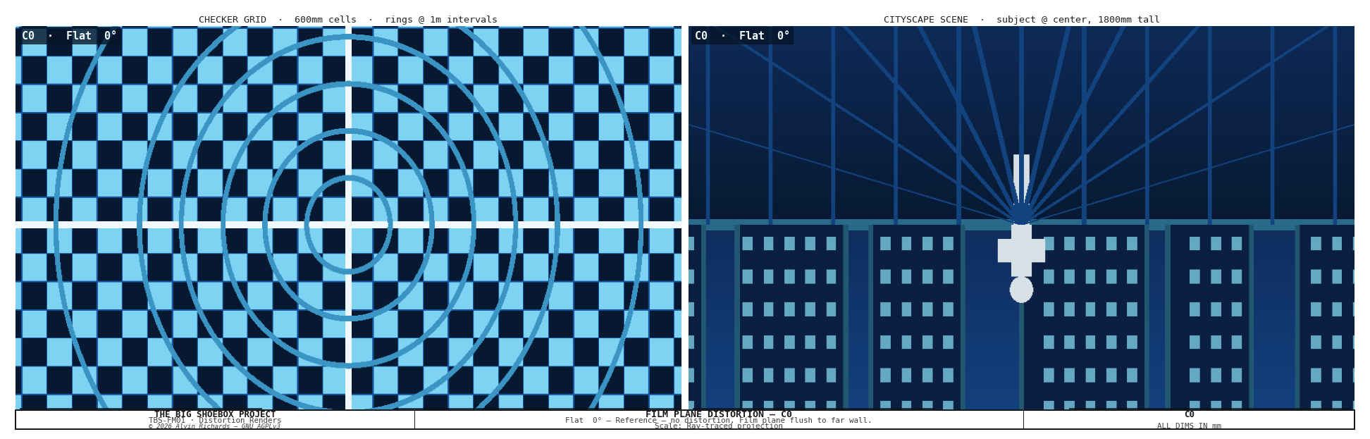
C0 — Flat (reference): Standard central projection. Vertical lines remain vertical, horizontal lines remain horizontal. The checker pattern is a regular perspective view.
C0 flat reference

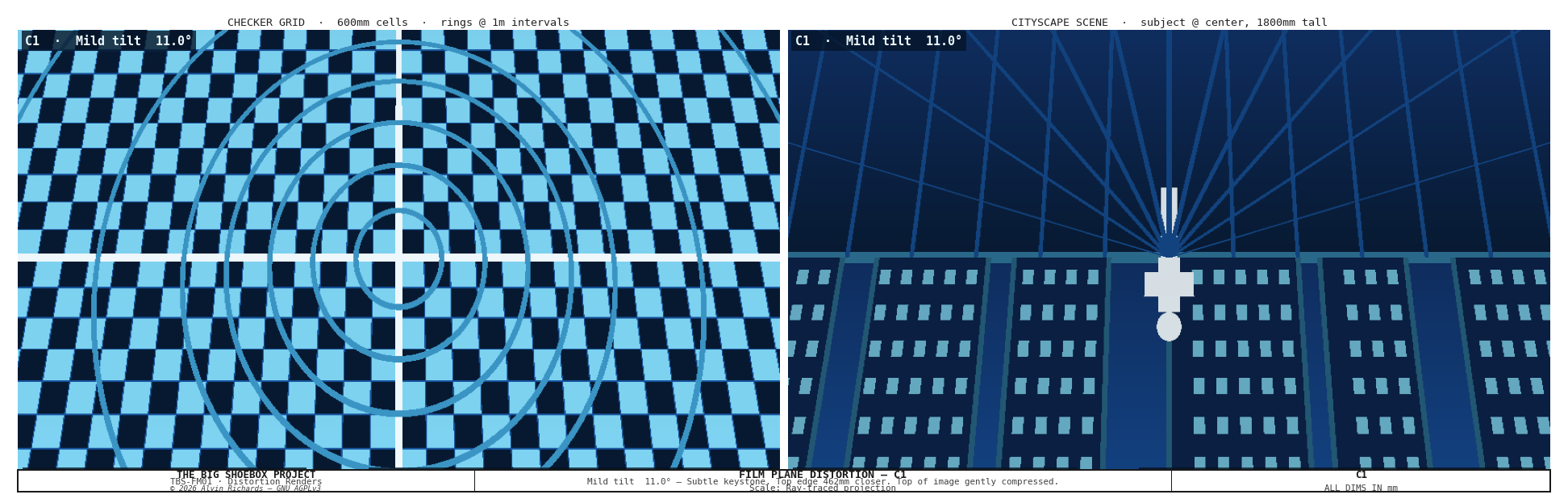
C1 — Mild tilt 5.6°: Subtle keystone. The top of the image is slightly compressed. Useful for compensating converging verticals when photographing tall subjects close to the camera.
C1 mild tilt

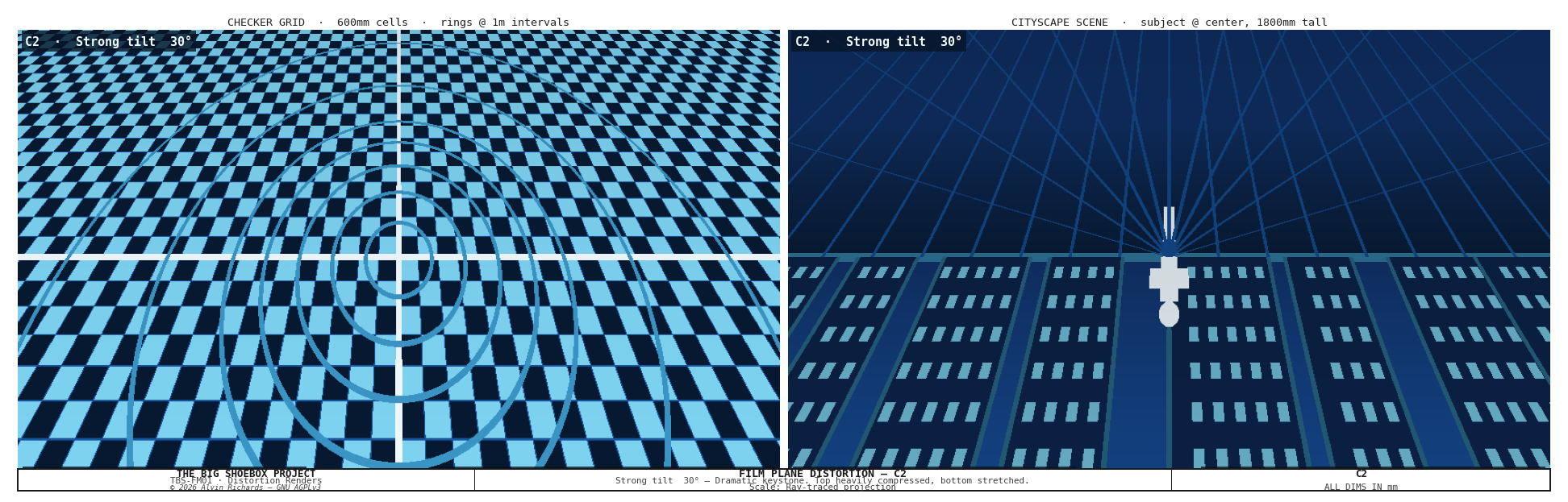
C2 — Strong tilt 17.5°: Dramatic keystone. Top of image has f ≈ 800mm — three times more compression than the bottom. Buildings appear to flare outward toward the base.
C2 strong tilt

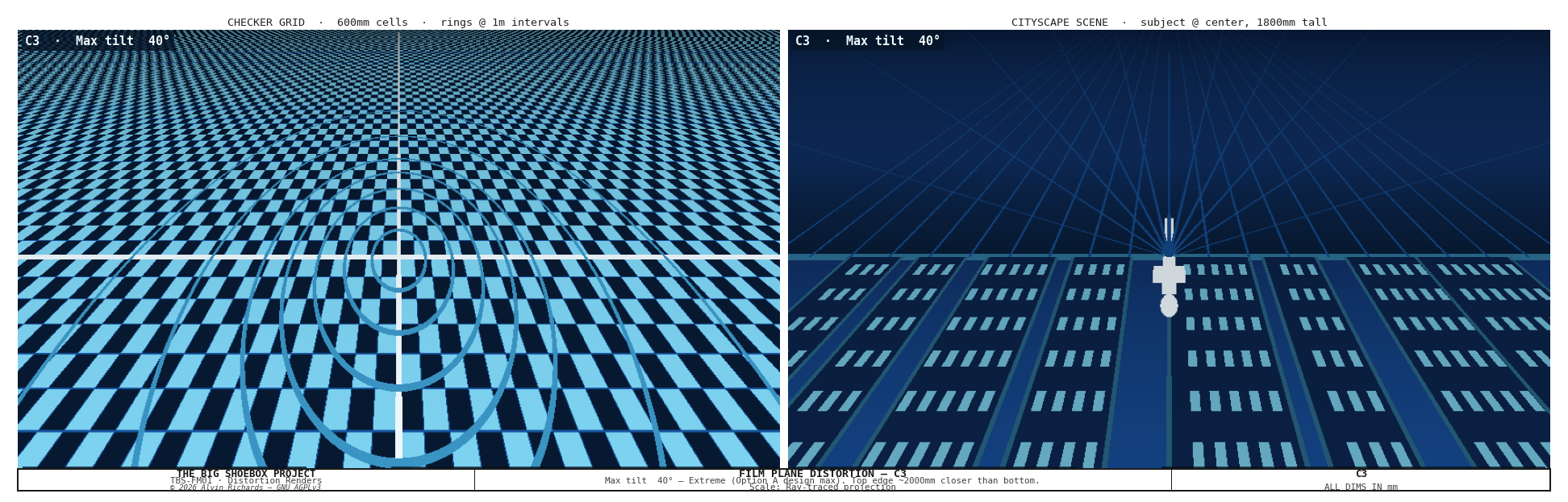
C3 — Maximum tilt 41.6°: Extreme effect. Top edge 100mm from pinhole wall — a 22× difference in effective focal length between top and bottom. The checkerboard transforms from squares at the bottom to near-horizontal slivers at the top.

Recommended for: wide open landscapes, aerial-perspective scenes, dramatic urban canyons.
C3 max tilt

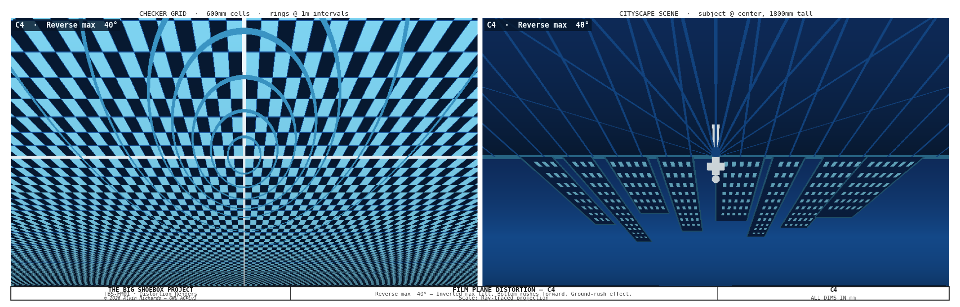
C4 — Maximum tilt down (reverse) 41.6°: The inverse of C3. Ground plane is compressed, sky dominates. Standing subjects elongate dramatically toward the bottom of the frame.
C4 reverse tilt

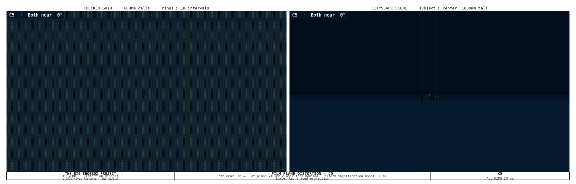
C5 — Both edges near (uniform close): The entire film plane is 100mm from the pinhole. Effective focal length drops from 2,362mm to ~100mm — a 23.6× reduction. Field of view becomes enormous.
C5 both near

C6 — Compound tilt + swing (superseded): under the original stretching design this was a diagonal twist (a ruled surface). Option A's fixed-size rigid plane cannot form a twisted surface, so this configuration is dropped — see film-plane-mechanism-report.md.

Summary Comparison

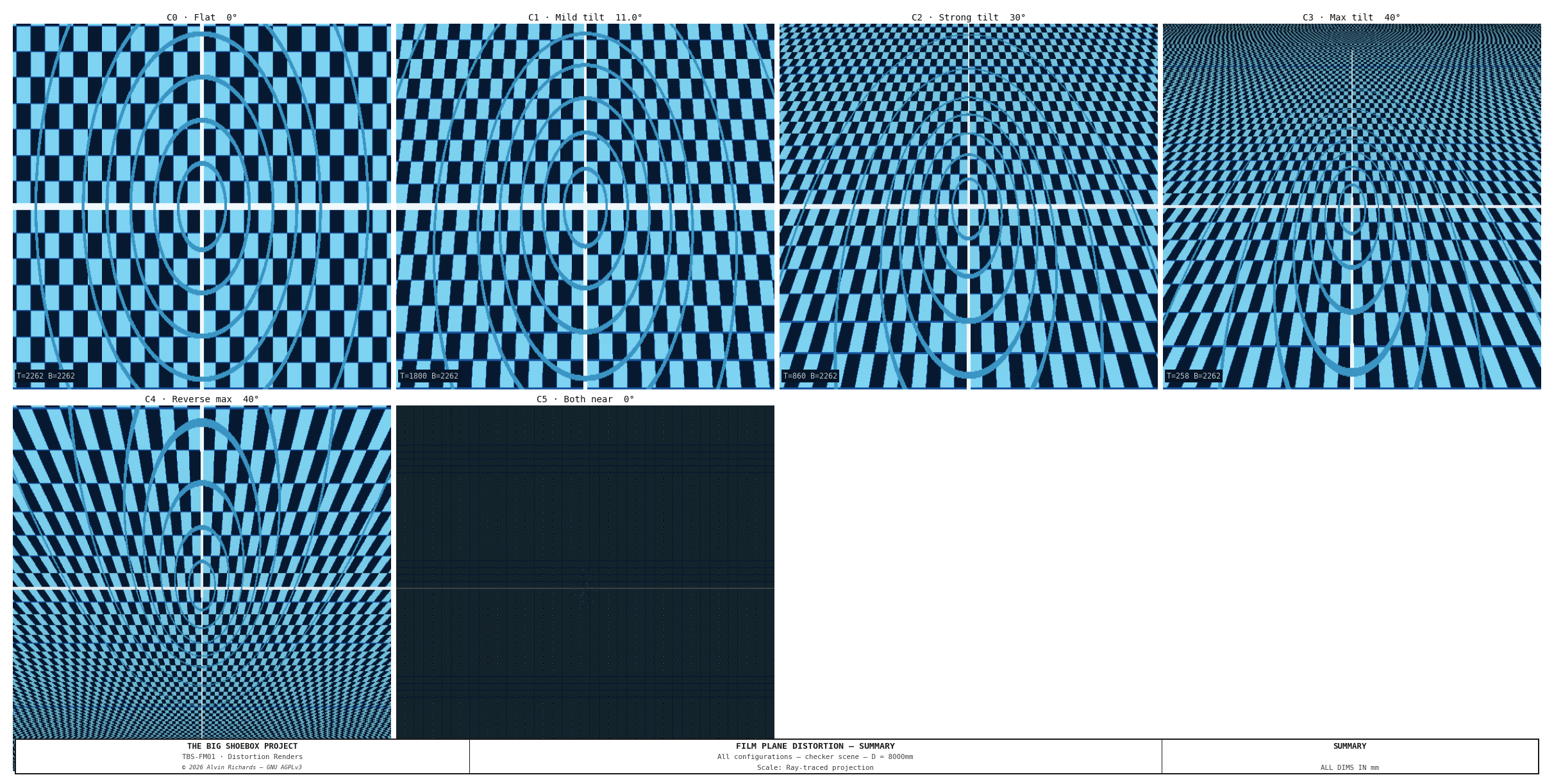
The six achievable flat configurations on a checker grid (D = 8,000mm):
Distortion summary


7. Engineering Drawings

Sheet Content
Sheet 1 — Plan view Top-down: 4-corner rail layout, film plane quad for each config; tilt hidden (into page), swing visible as diagonal
Sheet 2 — Elevations Left: side elevation showing tilt; Right: ceiling cross-section showing swing
Sheet 3 — Hardware detail Corner bracket assembly, HGR20+HGH20CA cross-section, rod-end spherical bearing, ACM panel hinge
Sheet 4 — Specification table All movement axes, 4-corner config table, full bill of materials

Sheet 1 — Plan view

Sheet 2 — Elevations

Sheet 3 — Hardware detail

Sheet 4 — Specification table

System context — container floor plan: The floor plan below shows the film plane rail positions (at Y=2,262mm, X=150–4,649mm) in the context of the complete TBS-001 interior, including left end zone (light trap), processing tray and perimeter walkway in the optical zone, and right end zone (4× IBCs in 2×2 stack, pump manifold on the Corridor Plumbing Panel and the filter skid on the Pinhole Wall Plumbing Panel).

TBS-001 Container Floor Plan — All Systems


8. Parts List

All items ship within the United States. Local Southern California pickup noted where available.

Structural & Rails

Item Spec Qty Source A Source B Est. Unit
Linear guide rail HGR20 2,200mm 4 Automation Overstock, Gardena CA McMaster-Carr #5901T777 $45
Rail carriage HGH20CA Flanged block 8 Automation Overstock / Amazon McMaster-Carr $18
Acme leadscrew ¾"-6 8 ft length 4 Roton Products (LA area) McMaster-Carr #6289K36 $95
Acme nut bronze ¾"-6 4 Roton Products McMaster-Carr #6289K512 $12
Handwheel 8" dia ¾" bore, cast aluminum 4 Grainger (Anaheim / LA / SD) McMaster-Carr #6440K64 $35
Locking collar SS316 ¾" bore 4 McMaster-Carr #6436K12 Fastenal (SoCal) $12
Corner bracket L-plate ¼" alum. plate, 6"×8" 4 Metal Supermarkets SoCal Online Metals $20
Rod-end spherical bearing GIR25-DO or equiv., 25mm bore 8 McMaster-Carr #60645K73 Amazon Industrial $22
Pivot pin SS316 Ø25mm × 200mm (slip-fit in 25mm bore) 8 McMaster-Carr (metric Ø25 SS shaft) Fastenal (SoCal branches) $8

Items in bold changed quantity vs the earlier two-beam design. The two 5,893mm T-slot beams have been removed.

Film Plane Frame

Item Spec Qty Source A Source B Est. Unit
Aluminum angle 2"×2"×3/16" 8 ft lengths 10 Metal Supermarkets SoCal Online Metals $22
Dibond ACM panel 4mm 4 ft × 8 ft sheets 6 Grimco, City of Industry CA Signwarehouse $85
Black EPDM foam tape 1"×½" 50 ft rolls 3 McMaster-Carr #8614K84 Grainger $28
Rosco Duvetyne 60" wide, 10 yd 1 B&H Photo Rosco direct $95
Aluminum piano hinge 72" 2" wide, 1/16" leaf 2 McMaster-Carr #1580A51 Grainger $28
6-mil black poly sheeting 10 ft × 100 ft 1 Home Depot (local, all SoCal) Uline $65
2" black Gorilla Tape 35 yd rolls 6 Home Depot / Target (local) Amazon $12

Muslin Clamp System

The photosensitive muslin is secured to the film plane frame by 92 cam-lever spring clamps spaced at 150mm centers around the full perimeter (30 per horizontal edge, 16 per vertical edge). Each clamp uses an over-center cam mechanism with a torsion spring to provide ~5N clamping force, gripping the muslin hem against the pinhole-facing leg of the aluminum angle frame through a 60A neoprene jaw pad.

The cam-lever design provides tactile snap-open/snap-closed feedback, critical for loading and unloading muslin in safelight (near-dark) conditions. The torsion spring biases each clamp closed at any tilt angle, so the film plane can be tilted or swung without clamps releasing.

Muslin wrap path: muslin drapes over the pinhole-facing leg of the 2"x2" angle, wraps around the outside corner, and a 100mm hem hangs down the perpendicular leg. The jaw presses the hem against the outer face of the pinhole-facing leg, ~10-15mm from the corner, providing direct tension.

Muslin clamp detail — Sheet 5

Item Spec Qty Source A Source B Est. Unit
Cam-lever spring clamp Toggle-style, ~5N, neoprene jaw 92 McMaster-Carr (Destaco equiv.) Amazon (generic toggle) $3-8
M5×16 SS socket head bolt A2-70 stainless 184 McMaster-Carr #91292A128 Bolt Depot $0.25
M5 SS Nylock nut A2-70 stainless 184 McMaster-Carr #93625A200 Bolt Depot $0.08
Neoprene strip 60A 35mm × 6mm, self-adhesive 1 roll (10m) McMaster-Carr #8614K44 Grainger $15

Clamp system estimated cost: $330 (generic toggle clamps) to $790 (Destaco-equivalent quality).

Optional Electric Actuation

Item Spec Qty Source A Source B Est. Unit
PA-14 linear actuator 12V, 20" stroke, 150 lb 4 Progressive Automations Amazon $185
12V 30A power supply Enclosed 1 Mouser Digi-Key $55
DPDT momentary rocker Panel-mount, 20A 4 Mouser Grainger $8

Estimated materials total (manual actuation): ~$2,400
Excludes fasteners, fabrication labor, and electric actuation option.
Net change vs two-beam design: removed 2× T-slot beams (–$416), added 2 leadscrews +$190, 2 handwheels +$70, 4 rod-end bearings +$88, 4 corner brackets +$80, 2 locking collars +$24 → net +$36.

Local SoCal Metal Sourcing

  • Metal Supermarkets — Anaheim (714-630-8463), Van Nuys (818-988-1301), San Diego (619-280-7600). Will cut to length on-site, no minimum order.
  • Grimco — City of Industry, CA. Sign-industry ACM panel supplier, large sheet stock.
  • Automation Overstock — Gardena, CA. Industrial surplus linear motion components; walk-in available.
  • Grainger — branches throughout LA, Orange County, San Diego. Same-day local pickup.
  • Roton Products — ships from the LA area; Acme screw stock cut to length.

9. Maintenance

Interval Task
Before each session Inspect muslin clamp engagement — all 92 clamps snapped closed
Before each session Verify all four locking collars are tight after repositioning
Before each session Check EPDM foam edge seal for tears or compression set
Monthly Lubricate HGR20 rails and HGH20CA carriage blocks (lithium grease)
Monthly Inspect Acme leadscrew threads and bronze nuts for wear
Every 6 months Check rod-end spherical bearings for play — replace if radial slop exceeds 0.2mm
Every 6 months Inspect Duvetyne blackout curtains for light leaks (pinholes, fraying)
Annually Check ACM panel hinge pins for corrosion; replace if stiff
Annually Verify rail mounting bolts for torque at all four rail positions
Before transport Lock all four corners at matching depth; tighten locking collars

10. Source References

  1. HIWIN HGR20 Linear Guideway — 20mm profile linear guide rail and HGH20CA carriage block specifications.
  2. McMaster-Carr GIR25-DO Rod-End Bearing — Spherical rod-end bearing specifications (25mm bore).
  3. Progressive Automations PA-14 — 12V linear actuator specifications (optional electric actuation).
  4. Tilt-Swing Front Board Report — Front board mechanism for combined distortion analysis.
  5. Equipment Layout Report — Rail positions and shadow-free zone verification.