Electrical Report¶
1. Purpose¶
This report specifies the complete electrical and environmental control systems for TBS-001: solar power architecture, battery bank, light trap vestibule, cooling, ventilation, interior lighting, and wiring. All systems run at 12V DC from a solar array with optional shore power backup, enabling fully off-grid operation.
See also: Operating Manual for step-by-step operational procedures.
2. System Overview¶
TBS-001 is designed for fully off-grid operation. All power comes from a solar array charging a LiFePO4 battery bank. Shore power (grid AC) is accommodated as an optional backup charging input only — the system operates identically without it.
All loads run at 12V DC - the one exception is the dedicated Circuit-E cooler inverter — see §7.6.
Interactive 3D model — the solar array, the panel internals (MPPT / fuse block / busbars / disconnects), the battery, the external power panel, the Circuit-E inverter, and the color-coded circuit runs out to each load. Drag to orbit, scroll to zoom.
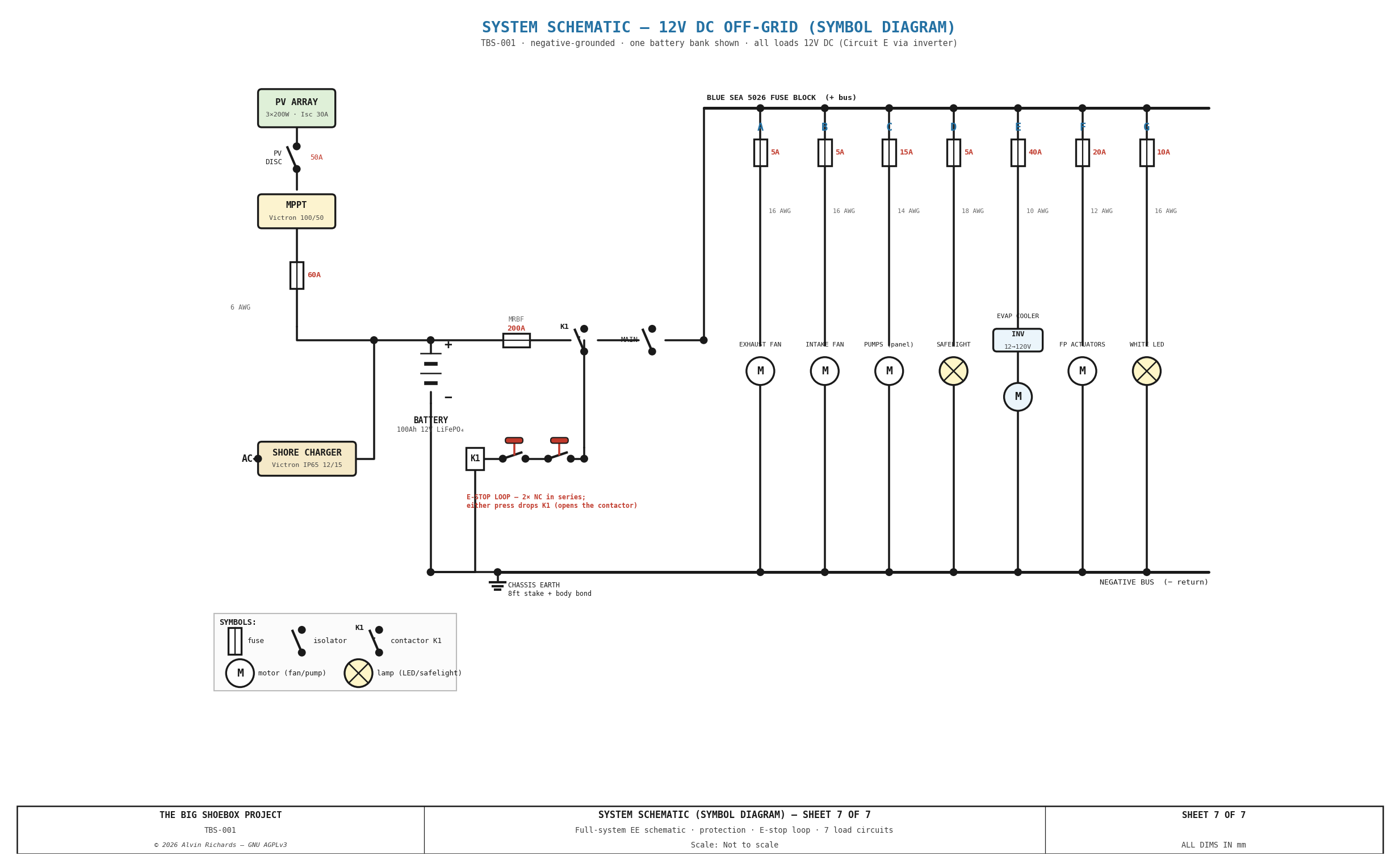
Sheet 7 — System Schematic (Symbol Diagram) The whole 12V DC system as a traditional symbol-based electrical schematic — every conductor traced from the PV array through the MPPT, battery, 200A MRBF, contactor K1, and main disconnect to the Blue Sea 5026 bus and the seven load circuits (A–G), with the NC E-stop loop and shore charger shown explicitly.
3. Power Budget¶
| Circuit | Device | Peak draw | Duty cycle |
|---|---|---|---|
| A | Ventilation fan — exhaust (6") | 60W | Continuous during processing |
| B | Ventilation fan — intake (6") | 60W | Continuous during processing |
| C | Water pumps P-01–P-05 (12V DC; 5× Shurflo 2088, run one at a time; single master switch) | 100W (one pump) | Intermittent (~30 min/print) |
| D | Safelight — interior + vestibule | 40W | Loading phase only (~45 min) |
| E | Evaporative cooler — Hessaire MC18M (120V AC) via 12V→120V inverter | 97W on 12V bus | Continuous during operation |
| F | Film plane actuators (optional) | 100W peak | Intermittent |
| G | White LED strip ×3 (general lighting) | ~76W | Non-operational periods only |
| Total peak (all on) | 533W | Not all simultaneous |
Circuit E is the only AC load. The cooler is a commodity 120V AC swamp cooler driven by a dedicated 12V→120V pure-sine inverter; its 85 W AC draw is 97 W on the 12 V battery bus (÷0.88 inverter efficiency). See §7.6 AC Isolation & Safety for the grounding/GFCI design.
3.1 Itemized Energy Budget (per print session)¶
Continuous loads by phase:
| Phase | Min | Active circuits | W | Wh |
|---|---|---|---|---|
| 1.6 Cooling warmup | 30 | Fan A (exhaust), Fan B (intake), Evap cooler | 217 | 108 |
| 1.7–1.8 Dark adaptation | 20 | Fan A (exhaust), Fan B (intake), Evap cooler, Safelight | 257 | 86 |
| 2 Load image plane | 45 | Fan A (exhaust), Fan B (intake), Evap cooler, Safelight | 257 | 193 |
| 3 Exposure | 37.5 | Fan A (exhaust), Fan B (intake), Evap cooler | 217 | 136 |
| 4 Development & wash | 20 | Fan A (exhaust), Fan B (intake), Evap cooler, White light | 293 | 98 |
| 5 Cleanup | 30 | Fan A (exhaust), Fan B (intake), Evap cooler, White light | 293 | 146 |
| Subtotal | 182 | 767 |
Intermittent loads (total runtime per print):
| Item | W | Min | Wh |
|---|---|---|---|
| Pumps (P-01 Blue) | 90 | 15 | 22.5 |
| Pumps (P-02 Brown) | 90 | 10 | 15.0 |
| Pumps (P-04 drain) | 90 | 5 | 7.5 |
| Actuators (optional) | 100 | 5 | 8.3 |
| Subtotal | 53 |
Total energy per session: 820 Wh (0.82 kWh)
Battery bank capacity (standard build, 1 pack): 100 Ah × 12V = 1,200 Wh (LiFePO4, 100% DoD) → 1.5 sessions per charge. The distribution busbar + fuse block are provisioned for a 2nd 100 Ah pack in parallel — a plug-in expansion (→ 200 Ah / 2,400 Wh / 2.9 sessions) requiring no rewiring; the 2nd pack is shown ghosted in the 2D/3D models.
Solar recharge: 600W array × 5.5 peak sun hours (Palm Springs) = 3,300 Wh/day → supports 4.0 sessions/day from solar alone.
3.2 Daily Use & Disconnected Endurance¶
Full treatment in the Daily Energy Report.
A representative daylight day of 3 sequential prints draws ~2,218 Wh (2 prints ~1,515; 4 prints ~2,921), dominated by the continuous fans + evaporative cooler (the cooler now drives the AC inverter, ~97 W on the 12 V bus); the Brown/Waste tote dump is gravity-assisted, tiny (~40 Wh), and incurred only at resupply (~every 4.7 days), not daily.
Disconnected endurance (no AC charge, solar top-up only): the system is clean-water limited, not power limited. With sun it is solar-positive (+1,082 Wh/day at 3 prints) → runs indefinitely on either 1 or 2 packs; the fresh Blue supply (1,800 L / 121 L net per print) caps a deployment at ~15 prints ≈ 4.7 days @ 3/day. Battery count sets only the cloudy-day reserve (1 pack ≈ 0.5 day, 2 packs ≈ 1.1 day) and the 4-print-day headroom — not the deployment length. The Black waste tote (1,000 L) is a parallel out-flow limit for fully self-contained field use.
4. Solar Array¶
| Parameter | Specification |
|---|---|
| Panels | 3 × 200W monocrystalline, 12V nominal |
| Configuration | 3 panels in parallel (12V, 30A combined Isc) |
| Mounting | Ground-mounted tilt frame (30° from horizontal) or roof rack |
| Orientation | Due south (azimuth 180°) |
| Cable | 10 AWG PV cable, MC4 connectors |
| Combiner | 3-way MC4 branch connector + 30A inline fuse per string |
| PV disconnect | Blue Sea 6006 DC battery switch (300 A / 48 V DC — sized against the array's ~30 A / ~22 V, since the panels are 3× parallel at 12 V nominal, not a high-voltage string), readily accessible at the power panel — isolates the array from the MPPT for service/fault (NEC 690.13). MC4 connectors are not load-break rated, and the external E-stop kills only the battery side — this kills the charge side |
| Wall entry | Via the external power-panel enclosure (§5.4) — the PV cables join the single sealed wall-bundle penetration |
| Approximate cost | ~$400 (panels) + ~$80 (mounting hardware) + ~$34 (PV disconnect — Blue Sea 6006) |
Siting: deploy panels on south-facing ground adjacent the container. For example, 30° tilt is optimal at Palm Springs latitude (33°N) for year-round average. If deploying in summer only, increase tilt to 20° for higher peak output.
5. Charge Controller and Battery Bank¶
5.1 Charge Controller¶
| Parameter | Specification |
|---|---|
| Model | Victron SmartSolar MPPT 100/50 charge controller |
| Max PV input | 100V OC, 50A charge current |
| Battery voltage | 12V auto-detect |
| Communication | Bluetooth (Victron Connect app) |
| Mounting | Interior short wall, adjacent main panel |
| Charge-line protection | 60 A ANL/MIDI fuse on the MPPT→battery lead, close to the battery; charge conductor sized 6 AWG |
| Approximate cost | ~$200 + ~$15 (charge fuse) |
The SmartSolar has a built-in load output (30A) for direct low-power 12V loads. The main high-current loads connect via the Blue Sea fuse block (see Section 7).
The MPPT delivers up to 50 A to the battery, so its battery lead carries far more than the array side — a dedicated 60 A fuse close to the battery protects that conductor (the 200 A main fuse is far too large to protect a charge-controller lead), and the conductor is upsized to 6 AWG to match.
5.2 Battery Bank¶
| Parameter | Specification |
|---|---|
| Chemistry | LiFePO4 (lithium iron phosphate) |
| Configuration | 1 × 100Ah 12V standard (busbar provisioned for a 2nd in parallel → 200Ah; plug-in expansion, no rewiring) |
| Usable energy | 1,200 Wh standard (2,400 Wh with the optional 2nd pack) |
| Discharge temperature | −20°C to +60°C operating — suitable for the hot container interior |
| Charge temperature | 0–45 °C — the BMS blocks charging above ~45 °C (cell protection); this drives the thermal siting below |
| Cycle life | 3,000–5,000 cycles to 80% capacity |
| BMS | Internal per-cell BMS (standard on Battle Born, Renogy LiFePO4 units) |
| Recommended brands | Battle Born 100Ah, Renogy 100Ah Core Series |
| Approximate cost | ~$350 (one unit); +$350 for the optional 2nd pack |
Thermal siting (required). Because the BMS inhibits charging above ~45 °C while a sun-exposed steel container can reach 60 °C interior, the pack is mounted low (floor level, in the coolest stratified air), shaded from the sun-baked shell, and kept in the evaporative-cooler / ventilation airflow path — so it stays inside the charge window during peak sun rather than locking out the solar charge. A commissioning temperature check confirms the bay stays < 45 °C under load (see Electrical Safety §4 #4).
One pack vs two — sizing rationale: a disconnected deployment is clean-water limited (~15 prints / ~4.7 days), not power limited (see §3.2), and the system is solar-positive, so one 100 Ah pack runs the standard deployment indefinitely on sun. The 2nd pack is a resilience upgrade — it extends the no-sun (cloudy-day) reserve from ~0.5 day to ~1.1 day and gives headroom for a 4-print day — not an endurance one. It plugs onto the busbar via its own terminal MRBF fuse — each parallel pack is fused at its own + post, so one pack's fault can't be back-fed by the other (the 2/0 cable and main disconnect are already sized for 200 Ah), so it can be added later without touching the wiring.
Why LiFePO4 and not NMC or lead-acid: - LiFePO4 does not exhibit thermal runaway — safe in an enclosed steel container that may reach 60°C interior - Full 100% depth of discharge usable (vs. 50% for lead-acid, 80% for NMC) - 3,000+ cycle life supports frequent deployments without degradation - No outgassing — can be used in an enclosed space without ventilation dedicated to the battery
5.3 Shore Power Backup Charger¶
| Parameter | Specification |
|---|---|
| Model | Victron Blue Smart IP65 12/15 |
| Input | 100–240V AC, NEMA 5-15 (standard US outlet) |
| Output | 12V DC, 15A (180W) |
| Full charge time from flat | ~7 hours standard (100Ah ÷ 15A); ~14h with the 2nd pack |
| Inlet | NEMA 5-15R weatherproof inlet in external power panel (pinhole wall exterior) |
| Output protection | 20 A fuse on the charger's DC output lead, close to the battery |
| Approximate cost | ~$150 + ~$5 (output fuse) |
Connect whenever shore power is available at a deployment site (campground hookup, venue power, generator) to top up the battery bank overnight.
5.4 External Power Panel¶
The solar PV inputs, shore power inlet, and the evaporative cooler's 120V AC output are carried on a fabricated flanged penetration box let into the pinhole wall, close to the electrical panel and battery bank inside.
| Parameter | Specification |
|---|---|
| Box | Fabricated sheet-metal flanged box — front face (exterior) + exterior flange, open to the container interior |
| Solar inputs | 3 × MC4 bulkhead pairs (IP67) — surface-mounted, sealed to the face |
| Shore power | 1 × NEMA 5-15R weatherproof inlet |
| Cooler output | 1 × NEMA 5-15R weatherproof duplex + in-use (bubble) cover (Circuit E — fed from the interior inverter, GFCI at the inverter §7.6) |
| Emergency stop | 1 × exterior red mushroom E-stop (kills the battery contactor from outside, §7.5) |
| Wall seal | Flashing + silicone bridging the corrugation crests around the flange — water-tight AND light-tight |
| PV disconnect | On the EP backboard (Blue Sea 6006, with the main disconnect + master pump switch) — not on this box |
| Location | Pinhole wall, X ≈ 1,250–1,590mm (just left of EP) |
| Approximate cost | ~$85 (fab box $60–100 + flashing/silicone $15–30) |
All four exterior interfaces are already weatherproof (MC4 IP67, weatherproof shore inlet, WR duplex under an in-use cover, IP65 E-stop), so they mount exposed — each surface-mounted and gasket-sealed to the box's front face, with the electrical attached from the container-interior side (the box opens inward). No secondary IP enclosure is needed. The container wall is corrugated, so the box's exterior flange can't seat flat: it is sealed to the wall with flashing over the corrugation crests plus a silicone bead — a seal that must be light-tight as well as water-tight (this is a pinhole camera; any perimeter gap or connector cavity fogs the print). Opaque front face + gasketed opaque devices + flashed flange give the light seal; the inlet/outlet socket cavities get a light-baffle behind them. Each device's wiring runs inside the container to the EP — the PV pairs to the Blue Sea 6006 disconnect on the EP backboard, the shore inlet to the charger, the cooler outlet from the inverter (Circuit E), the E-stop loop to the contactor. The cooler is unplugged and the cord stowed inside for transport. See the power panel detail drawing below.
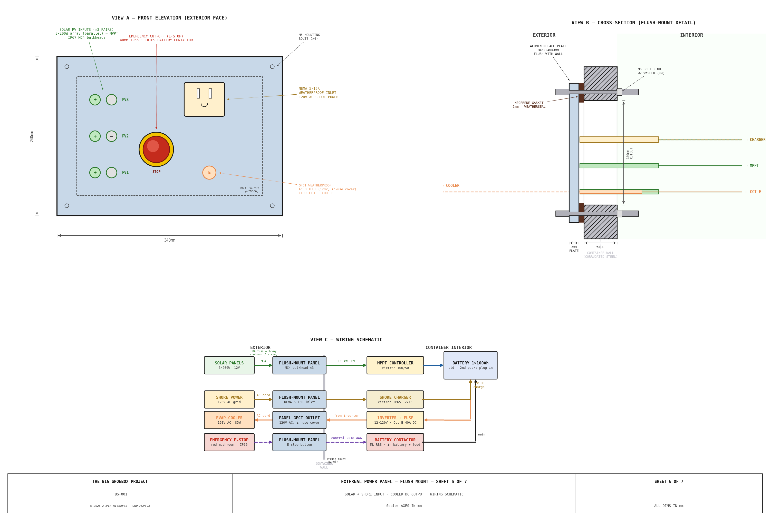
Detail drawing update to the penetration-box layout is pending (tracked in TODO) — it currently shows the superseded flush-plate geometry.
6. Interior Lighting¶
6.1 Two-Circuit Lighting Design¶
TBS-001 requires two mutually exclusive lighting modes:
- Safelight (Circuit D): Red 12V COB LED strip (Super Bright LEDs, in 981 channels + frosted diffuser), ceiling-mounted running near→far wall (X=520 / 2270 / 4170) plus the inner drum face, each shortened to clear the optical cone. Used during loading and development when photosensitive material is present. Red is cyanotype-safe (the process responds only to UV/blue). One 5m reel cut across the runs, ~40W total (3.3A — within the 5A fuse / 18 AWG, no bump), dimmable, always available. (Two of the three ceiling runs carry a parallel white strip — see §6.2.)
- White light (Circuit G): Three 12V COB LED strips (in aluminum channels + frosted diffusers) — two over the tray parallel to the two drum-side red safelights (X=520 / 2270), plus one running the length of the IBC/plumbing corridor to light the plumbing panel — for setup, maintenance, cleaning, and any non-operational work. ~76W total. Must be switched off before any photosensitive material is exposed.
The two circuits are independently switched — they are not interlocked, so the operator is responsible for ensuring Circuit G is off during operational phases. The pull-cord switches are positioned side by side for easy identification.
6.2 White LED Strip Specification¶
| Parameter | Specification |
|---|---|
| Type | 12V DC COB LED strip, 4000K neutral white (HitLights, 16.4 ft reels) |
| Runs | 3 ceiling runs in aluminum channels + frosted diffusers — two ~2,162mm over the tray, parallel to the X=520 / X=2270 drum-side red safelights, + one ~1,176mm running the IBC/plumbing corridor length (over the plumbing panel) |
| Power | ~76W (4.2 W/ft × ~18 ft) → ~6.3A |
| Luminous output | 426 lm/ft → ~7,670 lm total |
| Mounting | Surface aluminum channels (LED Profiles 981) on the ceiling |
| Dimmable | Yes (inline 12V PWM dimmer) |
| Circuit | G (10A fuse, 14 AWG) — 6.3A draw |
| Approximate cost | ~$84 (2 reels) + ~$81 (3× 8 ft channel) + ~$15 connectors/dimmer |
The three runs total ~5.5m of strip at 426 lm/ft → ~7,670 lumens across the ~14 m² floor area — approximately 548 lux, a solid workshop level for setup, maintenance, and cleaning. A 12V COB strip in an aluminum channel + diffuser gives an even, hot-spot-free ceiling wash (no discrete-fixture glare), runs cool, and is dimmable. At ~6.3A the Circuit-G feed is run in 14 AWG for margin and low voltage drop; the load still sits well inside the 10A fuse. True 12V-native (no inverter). Wired from Circuit G via the ceiling cable trunking.
6.3 Pull-Cord Switches¶
Two ceiling-mounted pull-cord switches are installed on the pinhole wall side of the container, accessible from the near walkway. Each switch controls one lighting circuit.
| Parameter | Specification |
|---|---|
| Type | 12V DC SPST pull-cord ceiling switch, 6A rated |
| Quantity | 2 |
| Position | Pinhole wall face, ceiling height |
| Switch 1 | Circuit D — safelight (red). Cord labeled "RED" |
| Switch 2 | Circuit G — white light. Cord labeled "WHITE" |
| Wire | Inline on respective circuit, between fuse block and load |
| Approximate cost | ~$8 each, ~$16 total |
The switches are positioned near the electrical panel, accessible from the near walkway. Pull-cord length is set so the cord hangs at approximately 1,500mm above the walkway deck — reachable without stretching.
7. Wiring Specification¶
7.1 Main Panel (Plywood Backboard + IP65 Enclosure)¶
An 18mm plywood backing panel (~700 × 2000mm) on the interior pinhole-wall face is the mounting surface every component fixes to. The DC-distribution terminals (fuse block + busbars + charge-line fuse) sit in a small IP65 weatherproof enclosure bolted to the plywood (its back panel is the plywood), sealing them against splash/dust from the water system; the MPPT, main disconnect, battery bank and inverter mount on the plywood outside it. It carries:
- Victron MPPT controller — on its own forward sub-panel, clear of the fuse-stack risers
- PV array disconnect — DC load-break isolator in the PV path (array → MPPT), wired in-line on the panel (NEC 690.13)
- Blue Sea 5026 12-circuit fuse block with busbars
- Battery positive and negative busbars, fed from the battery through a terminal-mount 200A MRBF fuse (on the battery + post, ≤180mm), a remote battery contactor (Blue Sea ML-RBS, tripped by either the exterior power-panel E-stop or an interior E-stop on the EP face, wired in parallel), and a main disconnect switch (Blue Sea m-Series 300A) — see §7.5
- MPPT charge-line fuse — a 60A ANL/MIDI fuse on the MPPT→battery lead at the busbar (§5.1)
- Interior E-stop — a red mushroom button (uxcell a19061100ux1510) on the EP face, paralleled with the exterior E-stop, so the contactor can also be tripped from inside the container (§7.5)
- Shore charger output terminals (with the 20A output fuse, §5.3)
- Circuit E inverter — Victron Phoenix 12/375 (GFCI version) mounted on the EP plywood panel (below the fuse gear, above the battery), with a short fused DC feed and its own DC disconnect (§7.6). Converts 12V DC → 120V AC for the evaporative cooler only.
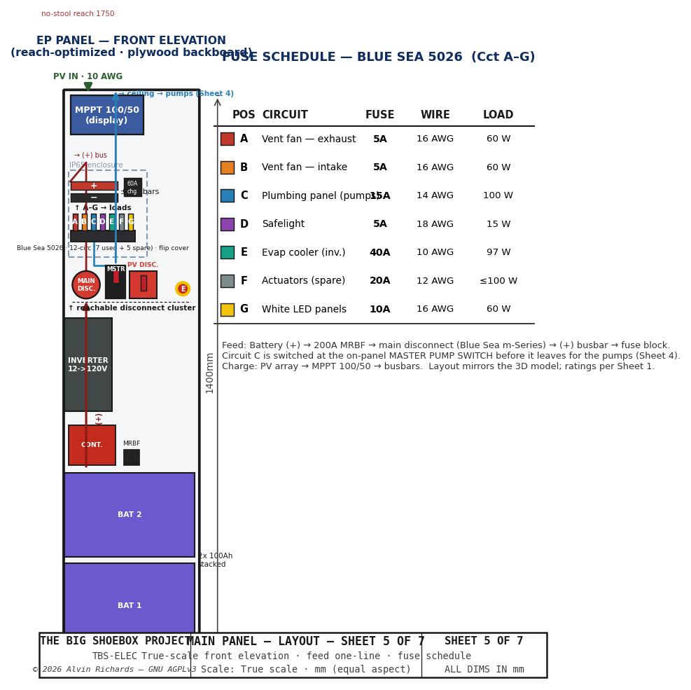
Sheet 5 — Main Panel Layout Front elevation of the EP plywood panel (mirrors the 3D model), reach-optimized so every service item is reachable without a stool: bottom-to-top the battery pair (low, set-and-forget), the inverter, a grouped disconnect cluster at chest height (main disconnect · Circuit-C master pump switch · PV disconnect · interior E-stop), the Blue Sea 5026 fuse block + +/− busbars in the IP65 enclosure (also chest height), and the MPPT display at the top of the reachable stack. The internal feed one-line is Battery(+) → 200A MRBF → main disconnect → (+) busbar → fuse stack → circuits (and the PV-charge path through the MPPT). A fuse schedule lists each position's circuit, rating, wire gauge and load.
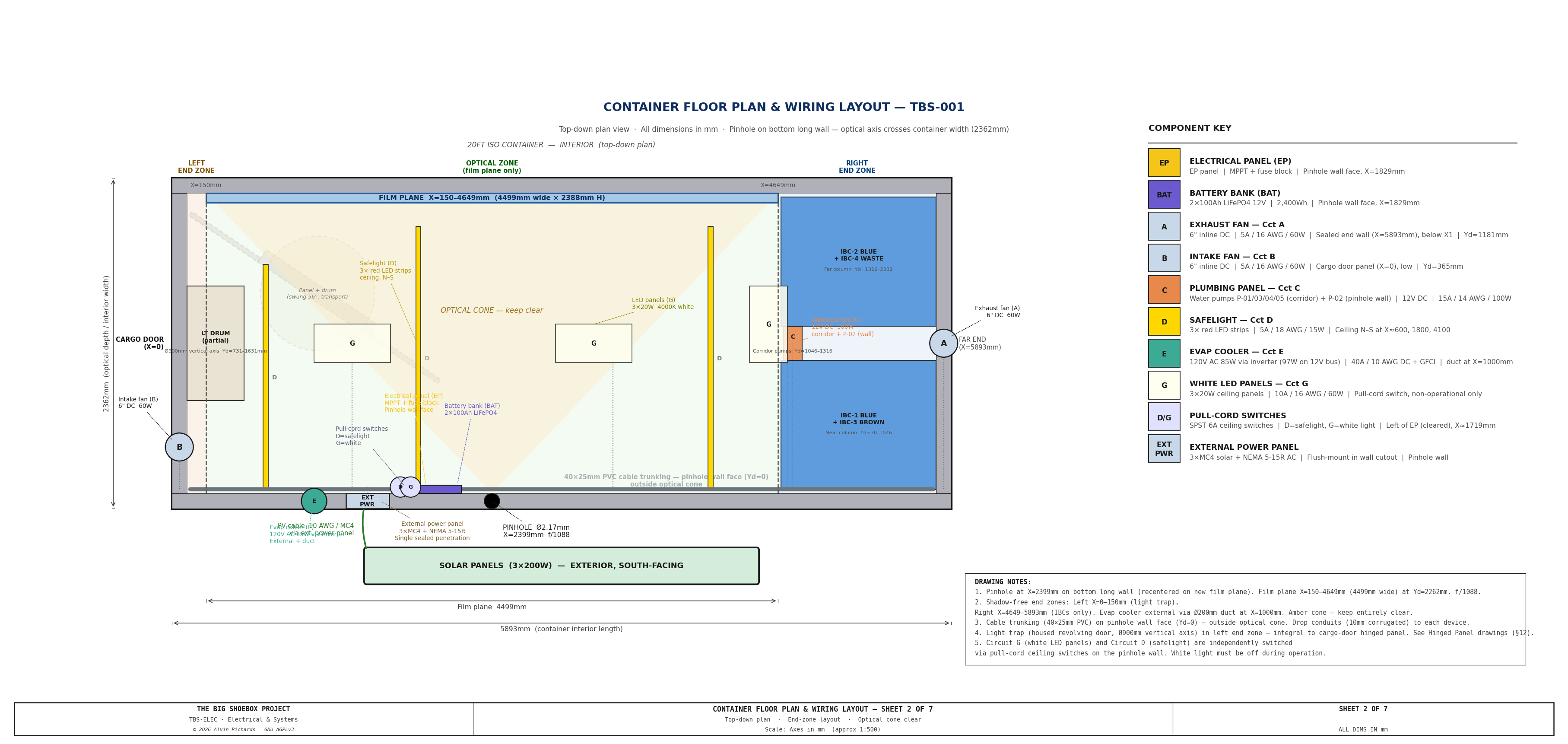
Sheet 2 — Container Wiring Layout Top-down floor plan (1:60 scale) showing all component positions, conduit routes, penetrations, drum panel, and connection points.
7.2 Circuit List¶
| Circuit | Device | Fuse | Wire gauge | Run length |
|---|---|---|---|---|
| A | Ventilation fan — exhaust (far end wall, high) | 5A | 16 AWG | ~2.5m |
| B | Ventilation fan — intake (panel-mounted, low) | 5A | 16 AWG | ~8m + flex connector |
| C | Water pumps P-01–P-05 (5× Shurflo, master switch) | 15A | 14 AWG feed + 16 AWG branches | ~5m feed (~8m to P-03) |
| D | Safelight (3× ceiling strips + drum) | 5A | 18 AWG | ~15m (3 branches + drum) |
| E | Evaporative cooler inverter (12V DC input) | 40A | 10 AWG | ~1m (battery → inverter) |
| E-AC | Inverter 120V AC out → panel cooler outlet | (GFCI at inverter) | 14 AWG / SJOOW | ~4m |
| F | Film plane actuators (optional) | 20A | 12 AWG | ~6m |
| G | White LED strip ×3 (general lighting) | 10A | 14 AWG | ~14m feed (3 runs ~5.5m lit, 6.3A) |
| — | Main battery fuse | 200A | 2/0 AWG | ~0.5m (battery to busbar) |
| — | PV array disconnect (load-break isolator) | — | 10 AWG | array → MPPT (at power panel) |
| — | MPPT charge-line fuse | 60A | 6 AWG | MPPT → battery (~0.5m) |
| — | E-stop control loop (exterior + interior, parallel) | — | 2× 18 AWG | both → ML-RBS trip |
7.3 Wiring Construction¶
Conduit: All DC wiring in gray corrugated conduit (Panduit or equivalent). Route in flat-profile cable trunking along the top corner rail of the container (40 × 25mm PVC trunking, UV-stabilized).
Connectors: - Interior connections: Anderson Powerpole 30A (red/black) — tool-free, industry standard for 12V DC - Exterior penetrations (fans, shore inlet): Deutsch DT series 2-pin weatherproof connectors — IP67 rated. (The cooler is 120V AC and terminates at the panel's GFCI-fed weatherproof outlet, not a DT connector — see Circuit E below and §7.6.) - Circuit B flex connector (panel-mounted intake fan): Fan B is mounted low on the swinging hinged panel. The wire run from the fuse block routes along the ceiling trunking to the fixed door frame, then crosses to the panel via a 1m coiled cable (16 AWG, 2-conductor, silicone-jacketed) with Deutsch DT 2-pin connectors at each end. The coiled cable must accommodate the ~56° transport swing about the pivot (with slack) without binding. Anchor the fixed end to the door frame top rail; anchor the panel end to the swinging frame near the pivot. The service loop hangs in the ceiling zone above and the wire drops down the panel to the low fan. - Circuit E (evaporative cooler, via inverter): The cooler is a 120V AC unit operating outside the container during sessions. The DC side is short: a fused 10 AWG feed (~1m) from the fuse block to the wall-mounted inverter, with its own DC disconnect. The AC side runs from the inverter's GFCI output along the ceiling trunking, down the pinhole wall to the external power panel, and terminates at the panel's weatherproof GFCI-fed NEMA 5-15R outlet (in-use cover). On the exterior, a 1.5m outdoor-rated SJOOW cord (NEMA 5-15P each end) connects the outlet to the cooler. The cord is unplugged and stowed inside for transport. Full grounding/GFCI design in §7.6. - Circuit C (water pumps P-01–P-05): The single 14 AWG Circuit-C feed is switched at a master pump switch on the Electrical Panel (EP) — one IP-rated manual cutoff for the whole pump circuit, upstream of everything — then runs along the ceiling trunking to a 12V DC distribution block (positive bus + shared negative bus) on the rear of the Corridor Plumbing Panel, which feeds each corridor pump directly via a short 16 AWG branch (~0.5–1m; 7.5A per pump). The four corridor pumps stack in a single column (bottom→top: ACC-01, P-01, P-02, P-05, P-03); P-04 (tray drain) taps the switched feed on the Pinhole-Wall filter skid. There are no per-pump switches — each Shurflo 2088 runs on its internal demand/pressure switch when its valves open, and the pumps are sequenced by opening the relevant valves (one at a time; simultaneous operation is not intended). The 15A circuit fuse protects the 14 AWG feed and covers a single pump (90W / 7.5A) with margin. The distribution block is in the wet zone — IP-rated, sealed, mounted above the spill line with drip loops (§7.5); the master switch is on the EP, clear of the wet zone.
Grounding: Bond the container steel body to the battery negative busbar using 4 AWG green/yellow wire at the main panel. Drive an 8-foot copper ground stake at the container foundation and connect to the main panel earth terminal. The inverter chassis, AC equipment-ground, and cooler ground bond to this same single point — see §7.6.
Labelling: Brady M210 wire labels at every terminal and every connector. Labels follow the circuit letter scheme (A–G) plus device description. Re-label after any wiring change.
7.4 Electrical Diagrams¶
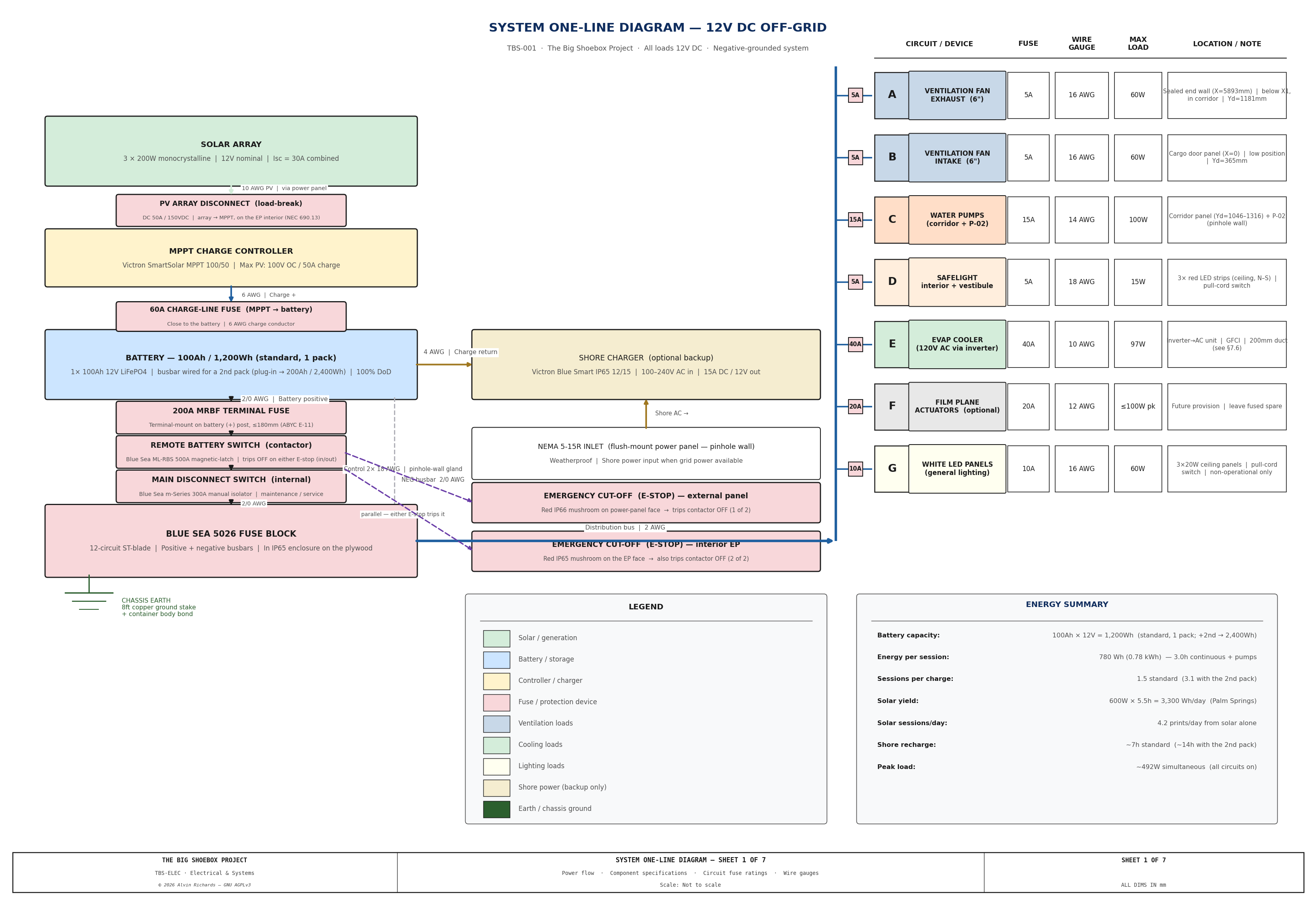
Sheet 1 — System One-Line Diagram Complete power flow from solar panels through controller, battery bank, fuse block, and out to each circuit. Wire gauges, fuse ratings, and component models labeled.
Sheet 3 — Pinhole Wall Interior Elevation Interior elevation of the pinhole wall face, looking from inside the container. Shows equipment mounting heights, cable trunking at the ceiling corner rail, drop conduits to each device, pull-cord switch positions with cord lengths, and ceiling-mounted LED panel locations.

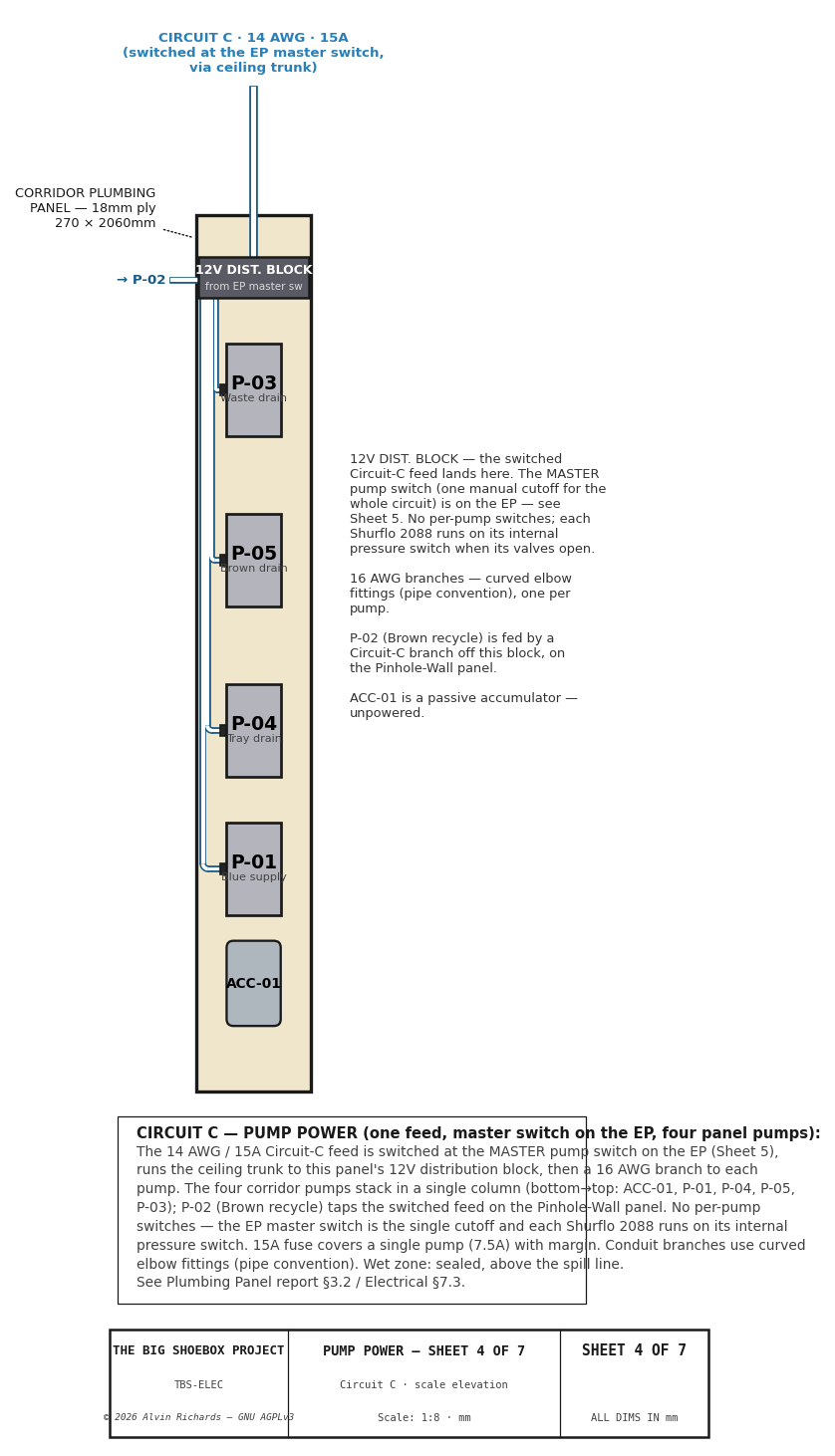
Sheet 4 — Plumbing-Panel Pump Power (Circuit C) Scale engineering elevation of the Circuit-C pump distribution on the corridor plumbing panel (matches the panel-layout elevation in the Plumbing Panel report §3.2): the switched 14 AWG / 15A feed (from the master pump switch on the EP — Sheet 5) → 12V distribution block → a 16 AWG curved-elbow branch to each of the four column pumps (bottom→top ACC-01, P-01, P-02, P-05, P-03; P-04 is fed on the Pinhole-Wall filter skid). No per-pump switches — the EP master switch is the single cutoff and each Shurflo runs on its internal pressure switch. See §7.3 (Circuit C) and the Plumbing Panel report §3.2.
Sheet 5 — Main Panel Layout
Front elevation of the EP plywood panel (the 2D companion to the electrical 3D model's power_core), reach-optimized so every maintenance item clears no-stool reach (≤1.75 m): bottom-to-top the battery pair, the inverter, a grouped disconnect cluster at ~chest height (main disconnect · Circuit-C master pump switch · PV disconnect · interior E-stop), the color-coded A–G blade-fuse stack on the Blue Sea 5026 with the +/− busbars in the IP65 enclosure at chest height, and the MPPT display at the top of the reachable stack, with the internal feed one-line (Battery(+) → 200A MRBF → main disconnect → (+) busbar → fuse stack → circuits) and the PV-charge path. Includes a fuse schedule (position / circuit / rating / wire / load). See §7.1 and §7.3.
7.5 Circuit Protection & Electrical Safety¶
This is a 12 V DC (extra-low-voltage) system whose only 120 V AC element is the dedicated cooler inverter (Circuit E, §7.6); everywhere else the dominant electrical hazard is DC short-circuit / arc / fire, not shock — see the dedicated Electrical Safety Report for the full hazard assessment. The 120 V AC cooler branch introduces a genuine shock hazard that is contained by the isolation/GFCI/bonding design in §7.6. The following protective measures are part of the build:
- Emergency cut-off — two E-stops (inside + outside) — a magnetic-latch battery contactor (Blue Sea ML-RBS, 500 A) sits in the battery (+) feed, downstream of the MRBF fuse and upstream of the internal disconnect. It is tripped by either of two E-stop push-buttons wired in parallel: a red weatherproof IP66 button on the external power-panel face (kills the DC system from outside, without entry) and a red IP65 button on the EP face inside (so an operator already in the container kills it without going out to the panel). Pressing either opens the contactor and de-energizes the entire DC system. The magnetic latch holds the contactor open at zero standby current; reset is at the contactor's manual lever. A low-current 2 × 18 AWG control loop (both buttons in parallel) runs to the contactor, the exterior leg penetrating the pinhole wall through a sealed gland.
- Battery main disconnect switch (Blue Sea m-Series 300 A) between the contactor and the distribution busbar — a manual isolator for maintenance / service de-energization (the 200 A fuse is overcurrent protection, not a switch).
- PV array disconnect — a DC load-break isolator (50 A / 150 VDC) on the array→MPPT line at the power panel isolates the charge side (which the battery-side E-stops do not reach) for service or fault; MC4 connectors are not load-break rated (NEC 690.13).
- MPPT charge-line fuse — a 60 A ANL/MIDI fuse on the MPPT→battery lead (6 AWG) close to the battery protects the charge conductor, which the 200 A main fuse is too large to cover.
- Main fuse at the battery terminal — a terminal-mount MRBF fuse on the battery + post (≤180 mm, per ABYC E-11) protects the main cable along its whole length.
- Battery terminal covers over both posts/busbar; use insulated tools at the busbar.
- Sealed wet-zone connections — pump circuits in the IBC corridor / tray end use IP-rated connectors (Deutsch DT or adhesive-lined heat-shrink), tinned marine-grade wire, and dielectric grease on terminals exposed to chemistry vapor. Anderson Powerpole is reserved for dry interior circuits only.
- Chafe protection — grommets / cable glands at every steel-shell penetration; + and − conductors paired/sheathed.
- Wet-zone wiring elevated above the spill line, with drip loops and no connectors at the lowest points.
- Equipotential bonding — the IBC frame, walkways, and tray-adjacent metal are bonded to the battery-negative reference (6 AWG), in addition to the shell bond in §7.3, so any positive-to-metal fault clears cleanly through a fuse.
7.6 Circuit E — AC Isolation & Safety¶
Circuit E is the system's only 120 V AC branch: a dedicated 12 V→120 V pure-sine inverter (Victron Phoenix 12/375, GFCI version) powering one outdoor, water-wetted evaporative cooler beside a grounded steel box. That combination — lethal AC + a wet appliance + a conductive enclosure — is a real shock hazard, contained by five code-anchored rules:
- Single neutral-ground bond (one source). The NEC permits exactly one neutral-to-ground bond in a system. The inverter is treated as a separately derived source: neutral is bonded to ground at the inverter only (the Phoenix GFCI version handles this internally) — no second bond downstream, which would either defeat the GFCI or cause nuisance trips. (NEC single-bond principle)
- GFCI on the AC output — mandatory. An outdoor, wet-location 120 V receptacle requires GFCI protection (NEC 210.8). The recommended inverter has a built-in GFCI outlet; the panel's cooler outlet is fed from it, protecting the operator handling a wet cooler.
- Equipotential bonding / effective fault path. The container shell, inverter chassis, cooler chassis, AC equipment-grounding conductor, and DC negative all tie to the single ground point (§7.3/§7.5). Any AC line-to-metal fault then has a low-impedance return that trips the GFCI/breaker instantly, so the steel shell can never become energized (NEC 250.110 / Art. 250 Part V).
- DC-side protection + positive isolation. The inverter's 12 V feed is fused at the battery (40 A, 10 AWG, ~1 m) with a dedicated DC disconnect, so the entire AC subsystem is hard-isolated whenever the cooler is not running — which is most of the time. The external E-stop (§7.5) also kills it with everything else.
- Galvanic isolation vs. bonding — by design. A transformer pure-sine inverter already isolates the AC live/neutral conductors from the 12 V battery side; rules 1–3 deliberately bond only the safety grounds to one point. Isolation (of the current-carrying conductors) and single-point bonding (of the grounds) are complementary, not in conflict.
Operationally: the cooler is plugged into the panel's in-use-covered GFCI outlet only during sessions; for transport the cord is unplugged and stowed and the inverter DC disconnect is opened. The Electrical Safety Report carries the full hazard assessment including this AC branch.
8. Parts List¶
All US/SoCal sources. Prices approximate as of 2026.
| Item | Spec | Source | Est. cost |
|---|---|---|---|
| Solar panels | 200W mono × 3 | Renogy (renogy.com), Amazon | ~$400 |
| MPPT charge controller | Victron SmartSolar MPPT 100/50 | altE Store (altestore.com) | ~$200 |
| LiFePO4 battery × 1 (standard) | 100Ah 12V (Renogy Core RBT12100LFP-US) | offgridstores.com / renogy.com | $306 |
| LiFePO4 battery — 2nd pack (optional, plug-in) | 100Ah 12V, parallel onto the busbar (no rewiring) + its own MRBF terminal fuse | same | +$375 |
| Shore backup charger | Victron Blue Smart IP65 12/15 | altE Store | ~$150 |
| Fuse block | Blue Sea 5026 ST Blade 12-circuit | West Marine (Torrance CA) / Amazon | ~$55 |
| 200A main fuse (terminal-mount) | Blue Sea MRBF on the battery + post (≤180mm, ABYC E-11) | Amazon | ~$25 |
| Battery main disconnect switch | Blue Sea m-Series 300A — manual isolator, contactor to busbar | West Marine (Torrance CA) / Amazon | ~$40 |
| Remote battery switch (contactor) | Blue Sea ML-RBS 500A magnetic-latch — in battery + feed, tripped by the external E-stop | West Marine (Torrance CA) / Amazon | ~$150 |
| External emergency cut-off (E-stop) | Red mushroom switch (uxcell a19061100ux1510) in a weatherproof control-station box (uxcell B07GN5P3NF, IP65, 78×71×64mm — ample for rain; upgrade to a gasketed IP66 box only if washdown-rated) + 2× 18 AWG control loop | Harfington / Amazon | ~$21 |
| Interior emergency cut-off (E-stop) | Red mushroom switch (uxcell a19061100ux1510), EP-face mount — paralleled to the exterior E-stop → ML-RBS trip | Harfington / Amazon | ~$13 |
| PV array disconnect | DC load-break isolator, 50A / 150VDC, panel-mount (array → MPPT; NEC 690.13) | AutomationDirect / Amazon | ~$40 |
| MPPT charge-line fuse | 60A ANL/MIDI + holder on the MPPT→battery lead; 6 AWG charge conductor | Blue Sea / Amazon | ~$15 |
| Shore-charger output fuse | 20A inline on the charger DC output lead | Amazon | ~$5 |
| Battery terminal covers (pair) | Insulating boots over + / − posts/busbar | Amazon | ~$10 |
| Sealed wet-zone connectors | Deutsch DT / adhesive-lined heat-shrink, pump circuits | Waytek Wire | ~$25 |
| Master pump switch (Circuit C) | 1× IP67 sealed rocker/disconnect, 12V 16A — single cutoff for the whole pump circuit, mounted on the EP | Amazon / Waytek Wire | ~$10 |
| Pump distribution block | 12V DC positive bus + negative bus (6-way), panel-mount on the rear of the Corridor Plumbing Panel, fed from the EP master switch | Blue Sea / Amazon | ~$15 |
| Dielectric grease | Marine-grade — chemistry-vapor terminal protection | Amazon | ~$10 |
| Tinned marine wire (wet-zone runs) | 14/16 AWG tinned copper, ~25ft | Waytek Wire | ~$30 |
| Cable grommets / glands | Steel-shell penetrations (chafe protection) | McMaster-Carr | ~$15 |
| Equipotential bonding kit | 6 AWG green/yellow + ring lugs — IBC frame / walkway / tray-metal to battery-negative | Amazon | ~$20 |
| Wiring kit | 14/16/18 AWG, 50ft each color | Amazon / Waytek Wire (waytekwire.com) | ~$80 |
| Anderson Powerpole connectors | 30A kit, 50 pairs | Powerwerx (powerwerx.com) | ~$40 |
| Deutsch DT connectors | DT 2-pin, 10 sets | Waytek Wire | ~$30 |
| Cable trunking | 40 × 25mm PVC, 5m lengths × 4 | Lowe's / McMaster-Carr | ~$40 |
| Corrugated conduit | Gray, 10mm ID, 10m | McMaster-Carr 7828K48 | ~$30 |
| EP plywood backing panel | 18mm, ~700×2000mm | Home Depot / Lumber yard | ~$60 |
| IP65 enclosure | ~200×220×140mm (fuse block + busbars) | Polycase / Amazon | ~$60 |
| Brady label kit | M210 with wire label cartridge | McMaster-Carr / Amazon | ~$80 |
| NEMA 5-15R inlet | Weatherproof outlet box | Leviton / Amazon | ~$25 |
| Cooler inverter | Victron Phoenix 12/375, GFCI version (12V→120V pure-sine, Circuit E) | Victron / Amazon | ~$210 |
| Inverter DC protection | 40A ANL fuse + holder + DC disconnect switch (inverter feed) | Blue Sea / Amazon | ~$40 |
| Panel AC outlet (Circuit E) | GFCI-fed weatherproof NEMA 5-15R + in-use (bubble) cover | Leviton / Amazon | ~$25 |
| Cooler power cord | 1.5m outdoor SJOOW, NEMA 5-15P each end | Amazon | ~$20 |
| Copper ground stake | 8ft × 5/8" diameter | Home Depot | ~$20 |
| 4 AWG ground wire | Green/yellow, 3m | AutoZone / Amazon | ~$15 |
| Solar mount + PV cabling + power-panel | Ground tilt frame (30°), MC4 PV cable + bulkheads, flush-panel plate + gasket + bolts, 2/0 AWG battery cable | various | ~$195 |
| Evaporative cooler | Hessaire MC18M, 120V AC, 1,300 CFM (run low), 85W, 16 lb | Hessaire / Amazon | ~$130 |
| Shade canopy | 80% shade cloth, 20 × 10ft | Amazon / Farm supply | ~$80 |
| Canopy frame | 1.5" EMT conduit + fittings | Home Depot | ~$120 |
| Ventilation fans × 2 | 150×150×50mm 12V DC axial panel fan, ~150–200 CFM (dimension-audit correction; not the AC Infinity S6 inline) | Amazon | ~$50 |
| 12V COB LED strip, 4000K, 16.4ft reel ×2 (L2712V-40D3-1630-U) + 6× LED Profiles 981 channel/diffuser (white + red) + connectors/PWM dimmers | white: 2× 2.16m tray + 1× 1.18m corridor (~7,670 lm / ~548 lux), 76W/6.3A, dimmable, true 12V | HitLights + LED Profiles | ~$84 strip + ~$162 channel + ~$15 |
| Red 12V COB LED strip, 5m reel (STN-B-BRED-O12A-08F5M-12V) | Circuit-D safelight — 40W/reel cut into 3 ceiling runs + drum (~40W/3.3A), COB 620nm, dimmable, cyanotype-safe, IP20 | Super Bright LEDs | ~$90 |
| Pull-cord ceiling switch, 12V 6A SPST | Inline switch for lighting circuits D & G | Amazon / Lowe's | ~$16 (×2) |
| Electrical system total | ~$3,464 | ||
| Shade canopy total | ~$236 | ||
| Cooling (cooler + inverter + DC protection + AC outlet + cord) | ~$262 | ||
| Systems grand total | ~$3,962 |
Electrical system total is the standard 1-pack build and matches the consolidated Master Shopping List §6 (Solar & battery $1,335 + Distribution & wiring $989 = $2,324, the authoritative electrical BOM). The optional 2nd battery pack adds +$375 (its own MRBF fuse). It includes ~$410 of circuit-protection / wet-zone-sealing hardware added per the Electrical Safety Report §5 (interior + exterior emergency cut-offs + battery contactor, disconnect switch, terminal-mount fuse, PV array disconnect, MPPT charge-line + shore-charger fuses, sealed connectors, bonding, grommets), plus ~$25 of Circuit-C pump-control hardware (1 master pump switch + distribution block).
9. Maintenance¶
| Interval | Task |
|---|---|
| Before each session | Check battery state of charge via Victron Connect app |
| Before each session | Verify all circuit fuses are intact on Blue Sea 5026 fuse block |
| Before each session | Test safelight (Circuit D) and white light (Circuit G) switches |
| Monthly | Inspect Anderson Powerpole connections for corrosion or looseness |
| Monthly | Check cable trunking clips and conduit routing for chafe |
| Monthly | Inspect Deutsch DT weatherproof connectors at fan penetrations; test the Circuit-E GFCI (cooler AC outlet) trip/reset |
| Every 6 months | Clean solar panel surfaces; check MC4 connector seals |
| Every 6 months | Inspect EPDM gasket on external power panel for compression set |
| Annually | Test battery BMS function (charge/discharge cycle under monitoring) |
| Annually | Inspect ground stake connection and measure earth resistance |
| Annually | Check pull-cord switch mechanisms for wear |
| Before transport | Disconnect evaporative cooler and stow per Equipment Layout §6.2 |
| Before transport | Verify all circuit breakers/fuses are off except safelight standby |
10. Source References¶
- Victron SmartSolar MPPT 100/50 — MPPT charge controller specifications.
- Victron Blue Smart IP65 12/15 — Shore power backup charger specifications.
- Blue Sea 5026 ST Blade Fuse Block — 12-circuit fuse block specifications.
- Battle Born 100Ah LiFePO4 — LiFePO4 battery specifications.
- Light Trap Selection Report — Revolving drum specification and commercial options evaluation.
- Hinged Panel Report — Panel construction, pivot, latch, and swing-mechanism specification.
- Water System Report — Pump circuits and water system electrical integration.
- Equipment Layout Report — Component positions and shadow-free zone verification.