Engineering Overview
1. System Assembly Overview
There are a number of discrete systems, color-coded in the diagram below. This view is shown from the optical axis, looking through the container wall. Each of these sub-systems has a detailed breakdown of construction, schematic, and other diagrams to show how each system is built, installed, used, and maintained. The 3D model below provides a simple way to view the whole system.
The major systems are:
- Electrical system (including solar charging sub-system)
- Water system and plumbing
- Lighttrap & Hinged panel
- Pinhole & Film plane mechanism
- Processing and Spray Bar
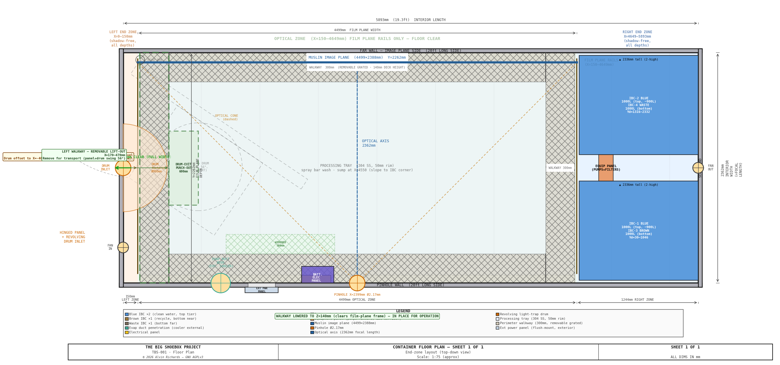
The container is split into three main areas
- Left: Lighttrap, hinged panel and walkway
- Center: Pinhole construction, processing tray & spray bar, film plane mechanism, electrical panels & battery pack and walkway
- Right: IBC stacking system, plumbing panel & plumbing and walkway
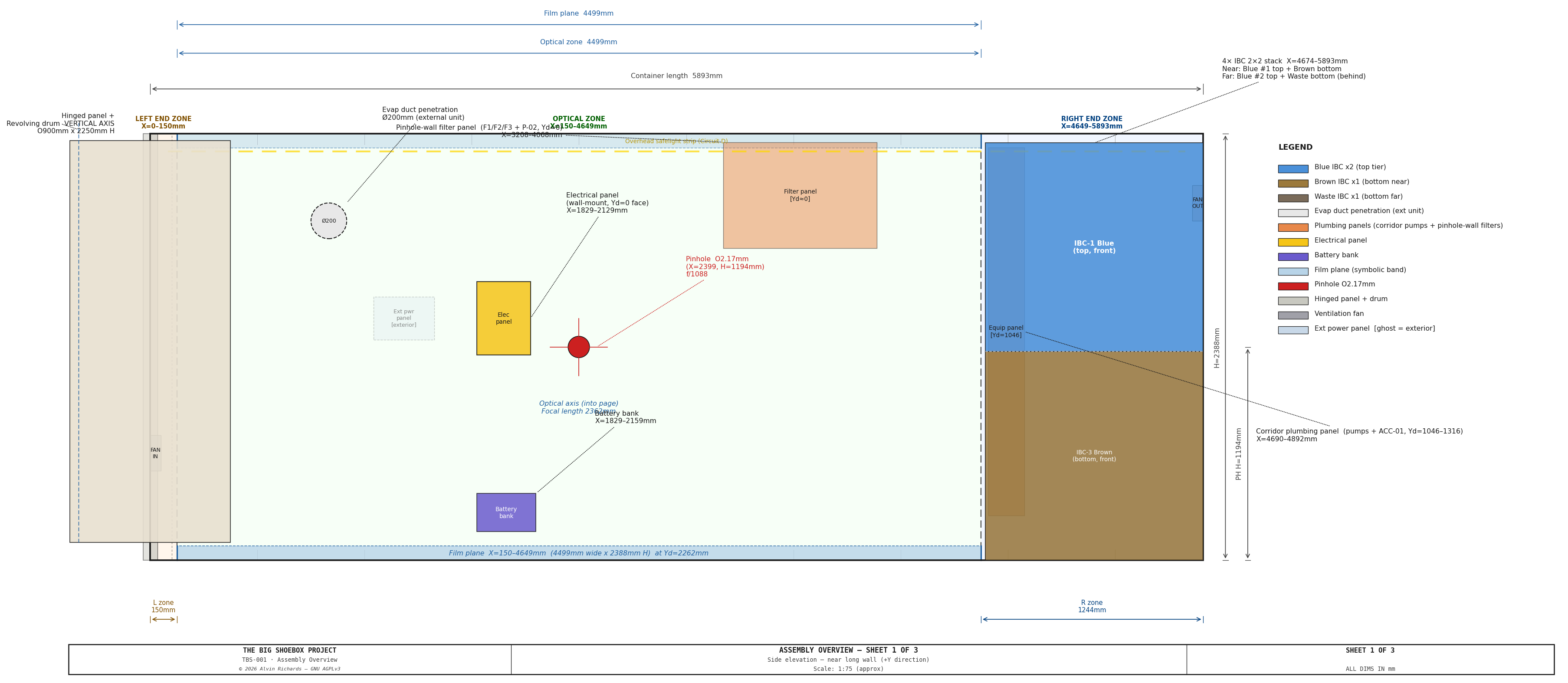
From the pinhole wall, looking toward the film plane, you can see the orientation of equipment placed on the inside of the container wall, relative to the pinhole. The equipment is positioned so as not to interfere with the optical cone. On the left the rotating light trap can be seen deployed in camera mode (as opposed to transport mode). On the right is the stack of IBC containers for clean and waste water.
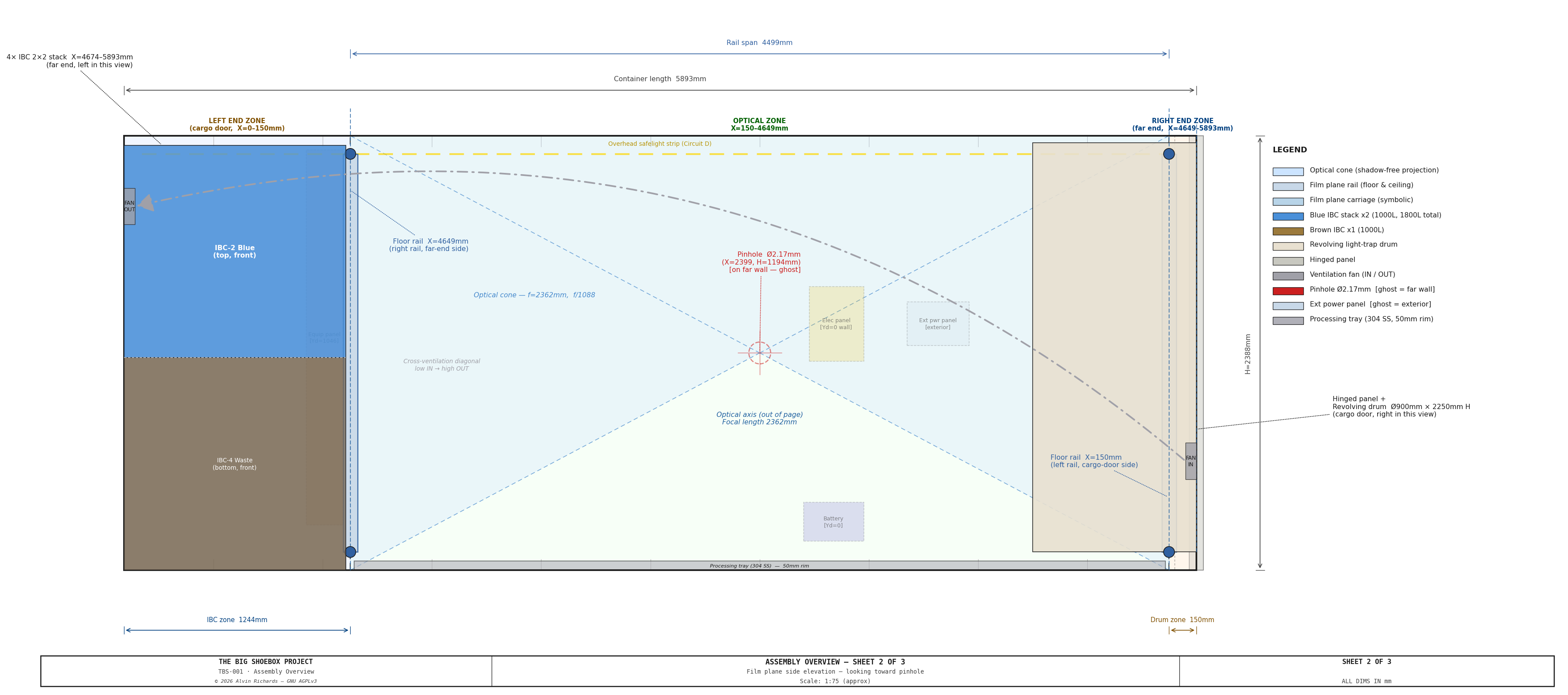
Second view is from the film plane wall, looking toward the pinhole. The X axis is mirrored (far end at left, cargo door at right). The orientation of the optical cone, film plane rails, and carriage can be seen, along with the ventilation path between the two ends of the container.
There are detailed construction reports for each of the major systems and their sub-systems.